
Electrical device with circuit status indicator

Active Publication Date: 2010-03-02
PASS SEYMOUR
View PDF20 Cites 6 Cited by
  • Summary
  • Abstract
  • Description
  • Claims
  • Application Information

AI Technical Summary

Benefits of technology

[0019]The benefits and advantages provided by the various embodiments of the invention will become more apparent

Problems solved by technology

Generally, the ground fault condition results when a person comes into contact with a line (or hot) conductor in the load circuit and an earth ground at the same time.
This situation can result in serious injury.
When such an imbalance is detected, a circuit breaker within the GFCI device is tripped to an open condition, thereby opening at least the line conductor to the load and removing power from the ground fault.
Unfortunately, there is a problem with GFCI receptacles of the type described above, in that the installer may erroneously connect the incoming AC source conductors to the load or feed-through terminals of the receptacle rather than to the source or line terminals.
Because of the nature of the internal wiring of a GFCI receptacle, this miswiring condition is not easily detected.
In reality, however, no such protection is being provided because the AC source has been wired directly to the receptacle outlets without passing through the internal circuit breaker of the GFCI device.
However, in the event that the receptacle has been miswired by connecting the AC source to the load terminals rather than to the line terminals, the LED is not extinguished when a ground fault condition occurs.
Unfortunately, however, the installer of the receptacle cannot necessarily be relied upon to understand the operation of the LED.
That is, the failure of the LED to extinguish after the TEST button is depressed may not be interpreted by the installer as an abnormal condition, particularly since the installer will observe the popping out of the RESET button.
Thus, the miswiring of the receptacle may not be detected and a dangerous condition may be allowed to persist.
As a result, visual indicators have led to confusion rather than to solution.
Unfortunately these indicators do not guide the user in what to do next.
Unfortunately given the variety of meanings of visual indicators, the indicator may cause confusion about how the test and reset buttons are to be manipulated and even whether or not the test passed.
As a result of the testing process not being user friendly, some users have shied away from testing, thus a device no longer affording protection remains in service.

Method used


Image

  • Electrical device with circuit status indicator
  • Electrical device with circuit status indicator
  • Electrical device with circuit status indicator

Examples


Embodiment Construction

[0036]Reference will now be made in detail to the present exemplary embodiments of the invention, examples of which are illustrated in the accompanying drawings. Wherever possible, the same reference numbers will be used throughout the drawings to refer to the same or like parts.

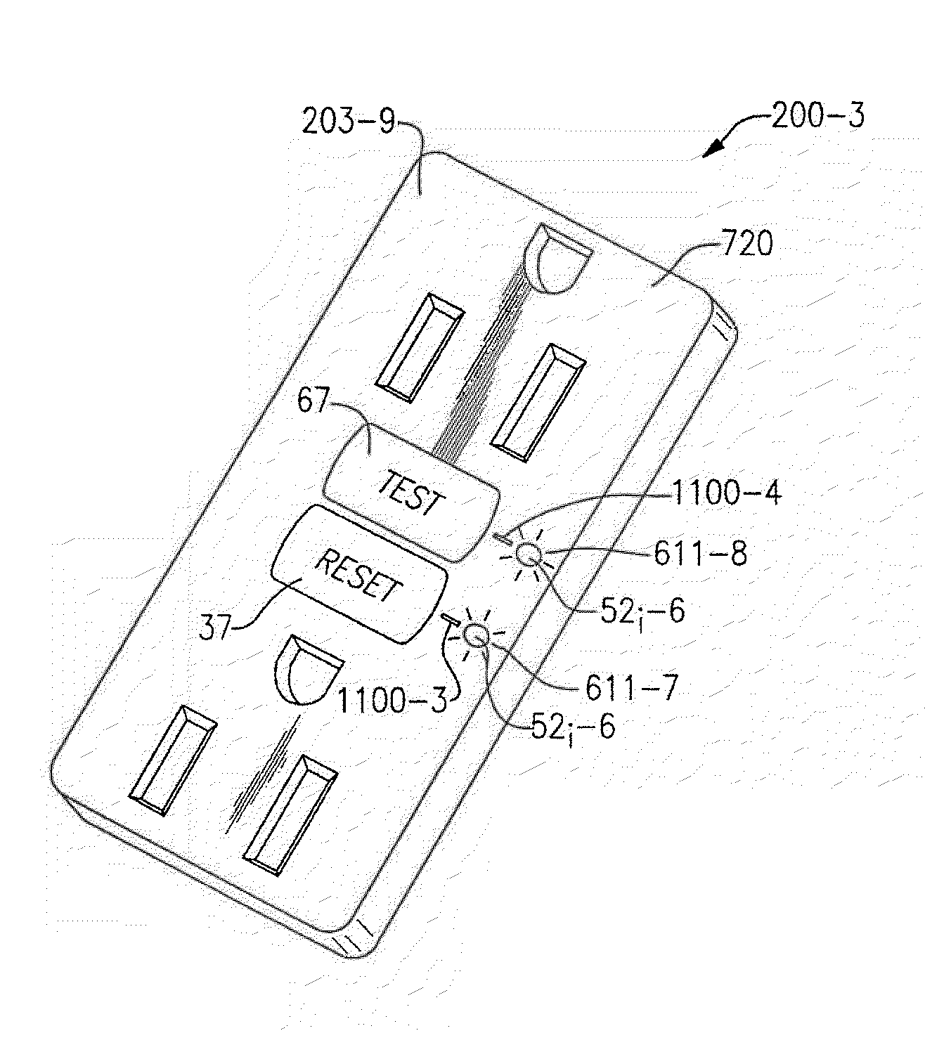
[0037]Embodiments of the invention are generally directed to an electrical wiring device that includes a GFCI or other type of circuit protection device, and an optical / visual circuit status indicator that is physically, visually, ergonomically or otherwise informatively associated with a RESET circuit activator and / or a TEST circuit activator of the device.

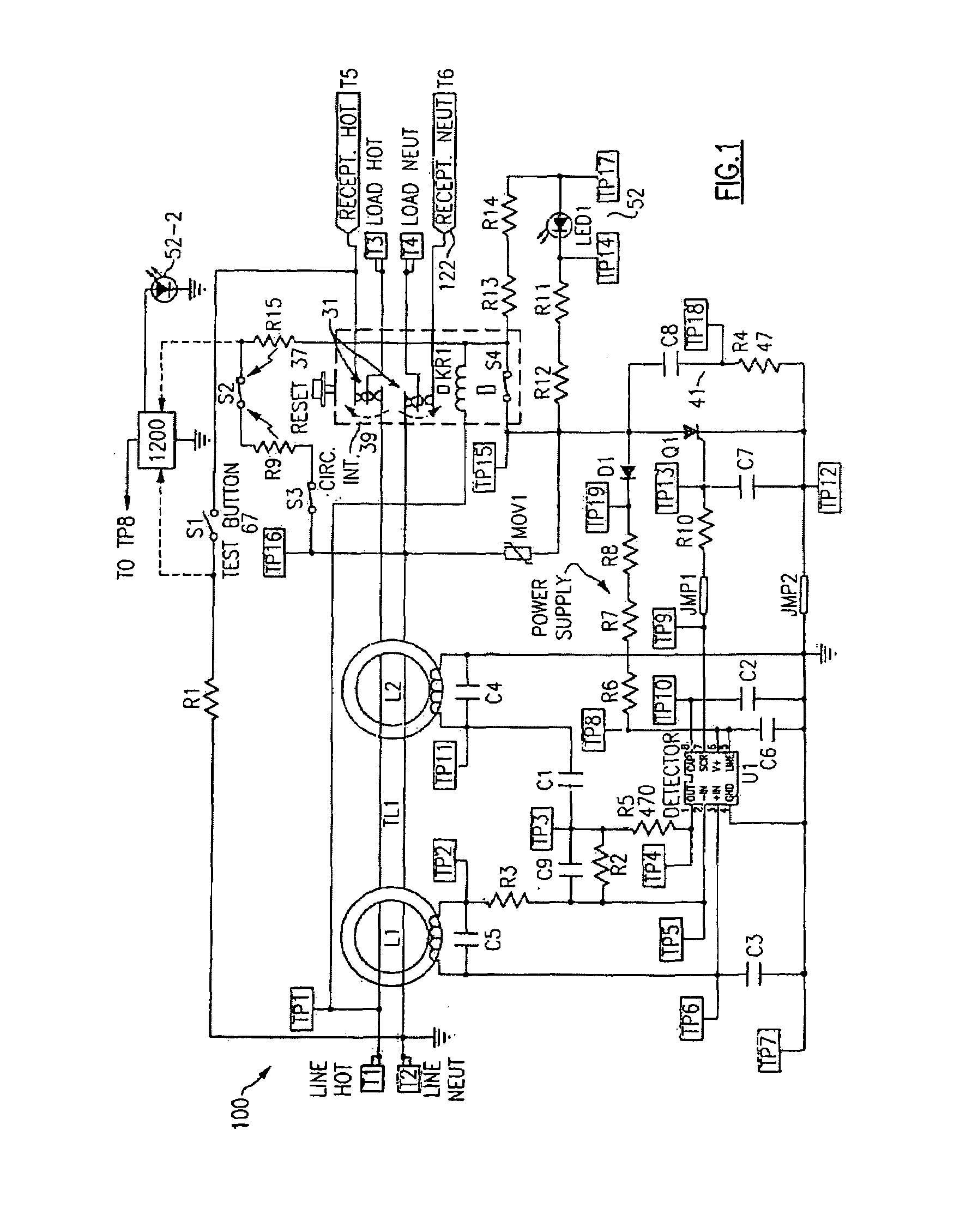
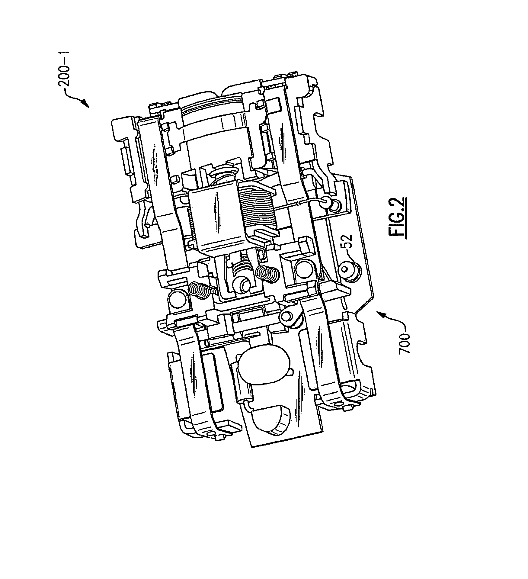
[0038]FIG. 1 shows an illustrative electrical schematic of a GFCI circuit 100 employed in a device 200-1 as shown in FIGS. 2-6, according to an exemplary embodiment of the invention. The particular GFCI circuit shown in FIG. 1 is not part of the invention per se. Other GFCI circuits, or for that matter circuits configured for other types of protective dev...


PUM


Abstract

An electrical control device including an electrical circuit, wherein the electrical circuit has a circuit protection component such as, e.g., a ground fault circuit interrupter (GFCI). The exemplary GFCI includes a TEST circuit activator and a RESET circuit activator, as well as a visual circuit status indicator indicia that is in an active (illuminated) state when the circuit is in a fault condition. The status indicator indicia is visually, physically, ergonomically or otherwise positively informatively associated with the TEST circuit activator and / or the RESET circuit activator. The positive informative association between the indicator indicia and the TEST circuit activator and / or the RESET circuit activator may be made by physical and / or visual boundaries or markings on a cover portion of the device or by integrally incorporating the indicia in the TEST circuit activator and / or the RESET circuit activator. The indicia may be a steady state or a blinking illumination. According to an aspect, a prompting indicator provides a prompting indicia for a user to activate the TEST circuit activator and / or the RESET circuit activator or replace a defective component of the device.

Description

RELATED APPLICATION DATA[0001]None.BACKGROUND OF THE INVENTION[0002]1. Field of the Invention[0003]Embodiments of the invention generally relate to the field of electrical wiring devices that include a circuit protection component such as a ground fault circuit interrupter (GFCI). More particularly, embodiments of the invention are directed to an electrical wiring device that includes a circuit protection component having an optical / visual circuit status or condition indicator, which is physically, visually, ergonomically or otherwise informatively associated with a circuit RESET or TEST activator component of the device.[0004]2. Description of Related Art[0005]Ground fault circuit interrupter (GFCI) devices are designed to trip in response to the detection of a ground fault condition in a load circuit. Generally, the ground fault condition results when a person comes into contact with a line (or hot) conductor in the load circuit and an earth ground at the same time. This situation...

Claims


Application Information

Patent Timeline
IPC IPC(8): H02H9/08H02H3/00
CPCH01H83/04H01H71/04H02H3/335
Inventor STRIBLEN, FABIENPACKARD, THOMAS N.GREENER, WILLIAM
Owner PASS SEYMOUR
Learn More