Compressor with oil bypass

a compressor and bypass technology, applied in the direction of machines/engines, rotary/oscillating piston pump components, liquid fuel engines, etc., can solve the problems of increasing the likelihood of compressor shutdown or failure, increasing the likelihood of oil circulation, and increasing the cost of cooling the shell with a water cooling tube wrapped around i

Active Publication Date: 2010-03-09
SHI APD CRYOGENICS INC +1
View PDF28 Cites 27 Cited by
  • Summary
  • Abstract
  • Description
  • Claims
  • Application Information

AI Technical Summary

Benefits of technology

[0016]It is also an object of the present invention to provide an oil bypass system that bypasses most of the oil around the motor, improve the oil-balancing effect, thereby reducing drag on the motor.
[0017]It is also an object of the present invention to provide an oil bypass system which reduces input power.
[0018]It is a further object of the present invention to provide an oil bypass system that reduces compressor vibration or compressor noise.
[0020]Yet another object of the present invention is to provide a compressor in which the variable orifice is automatically adjusted during operation of the compressor, allowing for operation at variable speeds.

Problems solved by technology

A problem with the oil cooling system is the flow rate and temperature of the cooling water are very important and must be monitored carefully.
Failure to monitor reduces the effectiveness of the oil separators, causes overheating, and increases the likelihood of compressor shutdown or failure.
Unlike the smaller compressor, for this type of compressor, cooling the shell with a water cooling tube wrapped around it is not effective.
However, a problem with the horizontal orientation is that more oil is circulated than is needed to lubricate the bearings and the “excess” collects in the bottom of the shell.
The excess oil flows through the “air” gap in the motor to the scroll, thereby putting significant drag on the motor.
The oil in the “air” gap and the resultant drag causes the motor to draw more power than when the compressor is operated in the vertical position.
A further problem with the horizontal orientation is greater vibration.
In addition to inherent vibration from the compressor, operating the standard Copeland scroll compressor horizontally, results in even greater vibration due to oil in the “air” gap.

Method used


Image

  • Compressor with oil bypass
  • Compressor with oil bypass
  • Compressor with oil bypass

Examples


example 1

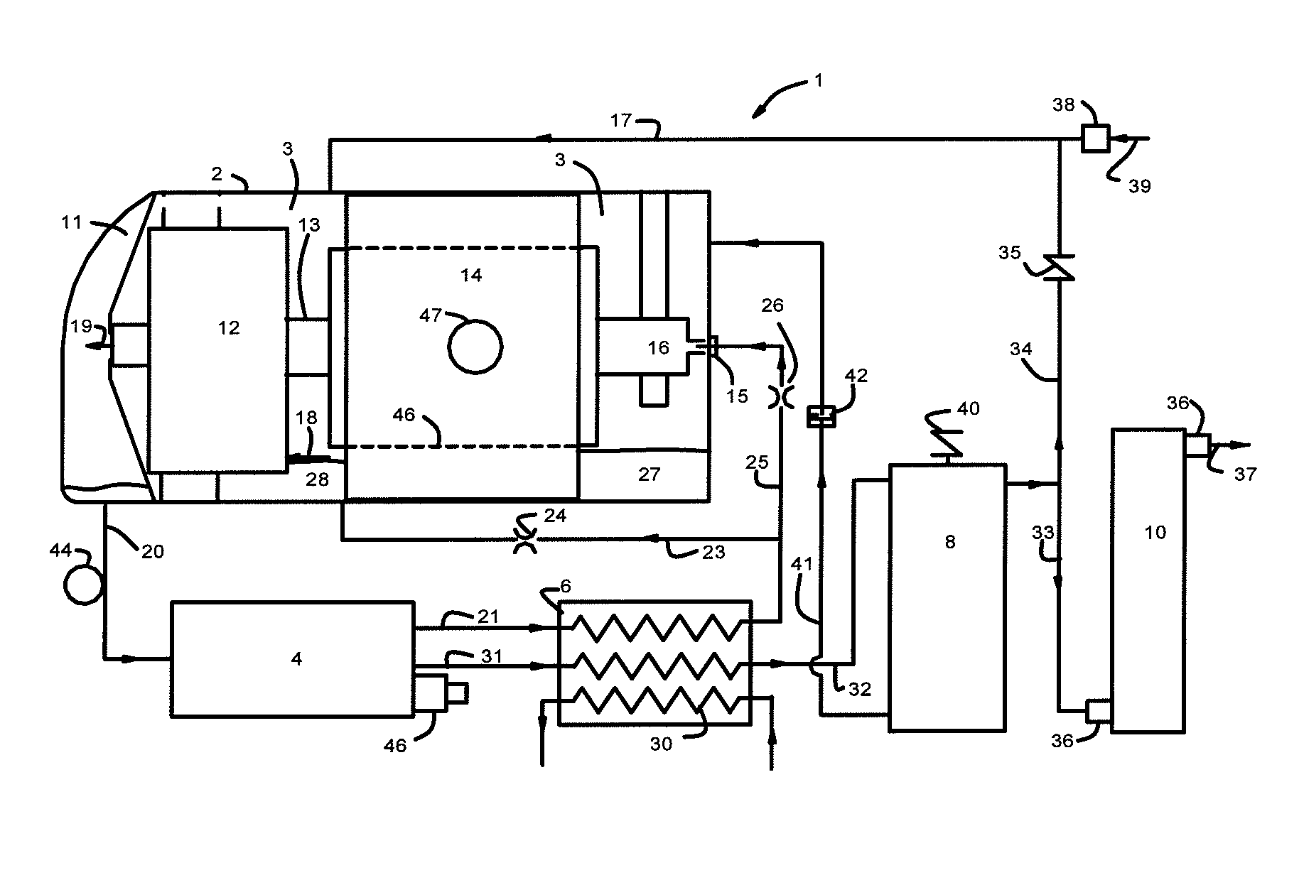
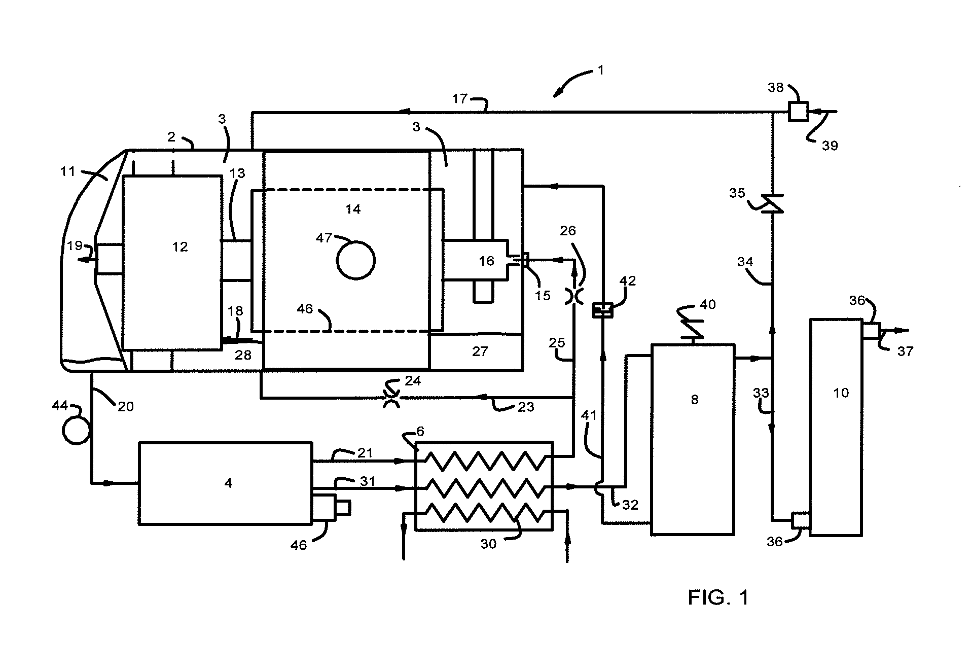
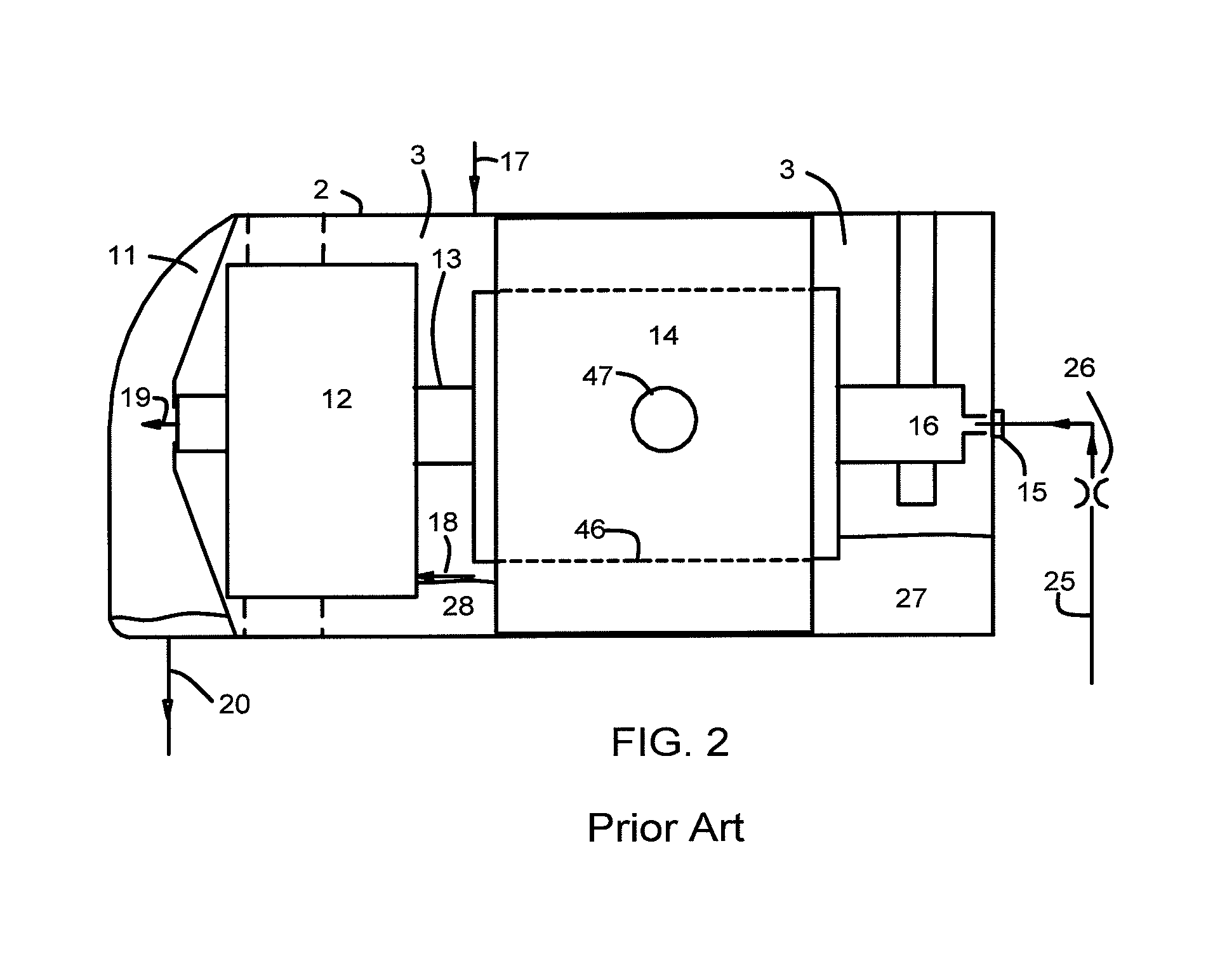
[0040]For a compressor that has a displacement of 338 L / min and an oil circulation rate of about 7 L / min, the input power at 60 Hz was reduced from 8,300 W to 8,000 W when 5 L / min of oil bypasses motor 14 by flowing through line 23.

[0041]The preferred embodiment of the invention relates to GM refrigerators and particularly Copeland scroll type compression refrigeration units used for air conditioners. However, the present invention may be adaptable for other types of scroll type compressors in compression type refrigeration units.

[0042]In alternative embodiments, the compressor could include additional valves, apertures or passages to control oil in excess of the amount needed to lubricate the bearings. Also, it is also to be understood that the phraseology and terminology used herein is for the purpose of description and should not be regarded as limiting.


PUM


Abstract

An oil lubricated compressor which includes a bypass oil line connecting respective oil paths upstream and downstream of the motor. The bypass oil path permits oil to be detoured around the motor in a tube that is external to the compressor shell and flows back into the shell near the scroll inlet. The oil bypass line returns “excess” oil directly to sump 28, rather than having it flow from sump 27 to sump 28 through an air-gap, thereby reducing both the drag on the motor and the input power.

Description

BACKGROUND OF THE INVENTION[0001]This invention relates generally to helium compressor units for use in cryogenic refrigeration systems, operating on the Gifford McMahon (GM) cycle. More particularly, the invention relates to an improved oil cooling structure for a scroll type oil-lubricated compressor unit adapted to compressing helium by orienting it horizontally.[0002]A refrigeration compressor has a need for lubrication of moving parts such as bearings and gears. These compressors contain oil sumps to direct oil from the sump to each lubrication point. Oil-lubricated air conditioning compressors have become standard for delivering pressurized helium to GM type cryogenic refrigerators. The ability to use these relatively inexpensive but reliable compressors results from developing methods to cool the helium as it is being compressed, and the development of oil separators and adsorbers that reliably keep oil out of the cold expander of a GM type refrigeration system. Because heliu...

Claims


Application Information

Patent Timeline
Patent Type & Authority Patents(United States)
IPC IPC(8): F01C21/04F04C29/02
CPCF04C18/0207F04C23/008F04C29/028F04C2220/22F04C2240/809F04C2270/12
Inventor DUNN, STEPHEN
Owner SHI APD CRYOGENICS INC
Why Eureka
Try Eureka