Fiber fabric and composite material

a fiber fabric and composite material technology, applied in weaving, shock absorption devices, vehicular safety arrangments, etc., can solve the problems of poor production efficiency in the case of producing composite materials with a large thickness, disadvantages in improving the poor strength of composite materials, so as to improve the production efficiency of overlapped sheets and excellent moldability and strength

Inactive Publication Date: 2010-03-09
TOYOTA IND CORP
View PDF13 Cites 25 Cited by
  • Summary
  • Abstract
  • Description
  • Claims
  • Application Information

AI Technical Summary

Benefits of technology

[0008]Accordingly, it is an objective of the present invention to provide a fiber fabric which has excellent moldability and strength, and improves the production efficiency of an overlapped sheet the thickness of which is increased by overlapping the fiber fabrics, and to a composite material made of a fiber reinforced resin using the fiber fabric.

Problems solved by technology

However, since the fabric is woven only by the warp and the weft, threads are bent and meander, and it is disadvantageous in view of improving the strength of the composite material.
However, in the case that the crimp exists although it is small, it is disadvantageous for improving the strength of the composite material.
However, since the fabric in the Japanese Laid-Open Patent Publication No. 7-243149 is the fabric having a single layer sheet shape, the production efficiency in the case of producing the composite material having a large thickness is not good.

Method used


Image

  • Fiber fabric and composite material
  • Fiber fabric and composite material
  • Fiber fabric and composite material

Examples


first embodiment

[0050]A description will be given of a first embodiment according to the present invention on the basis of FIGS. 1A to 5B.

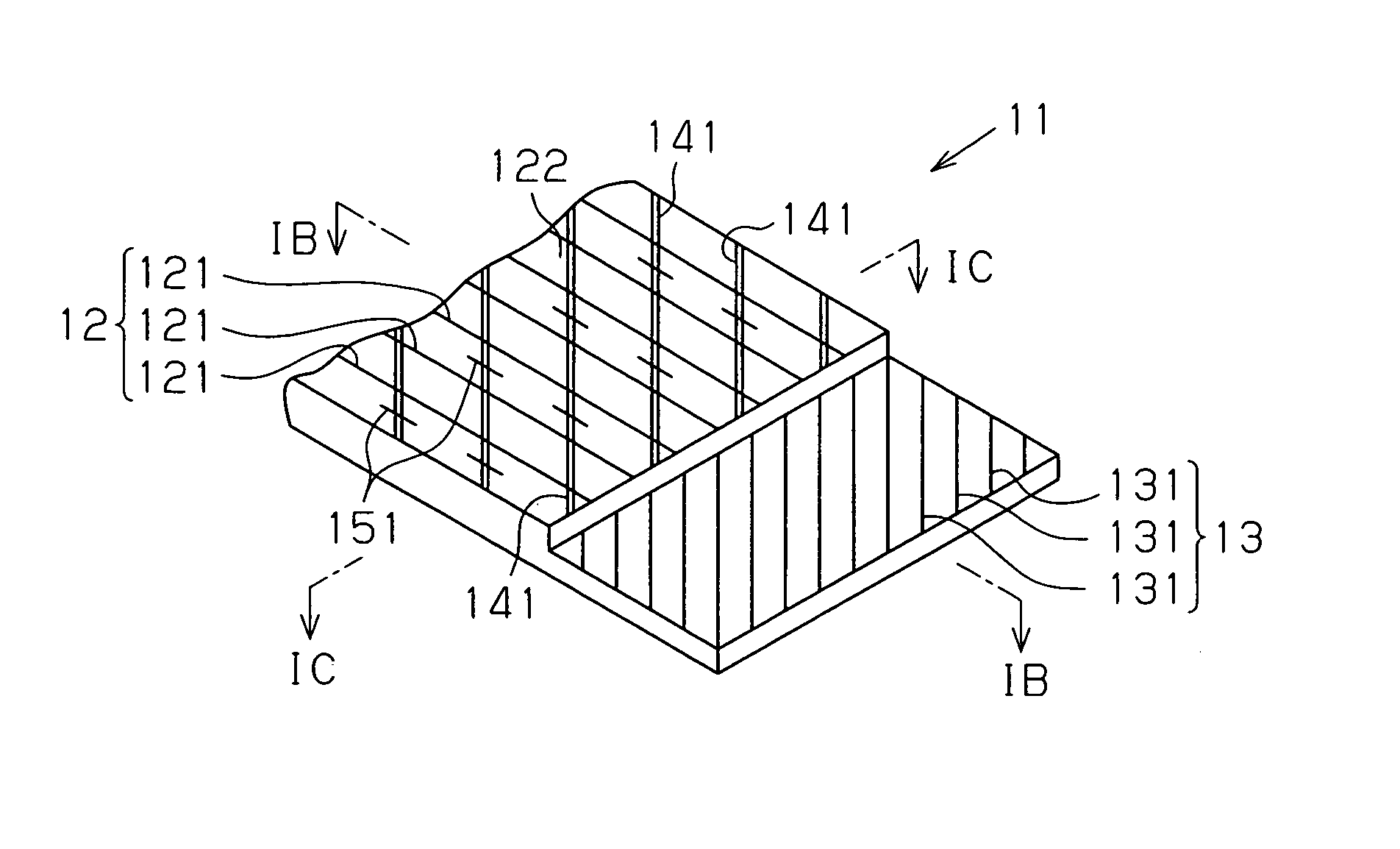
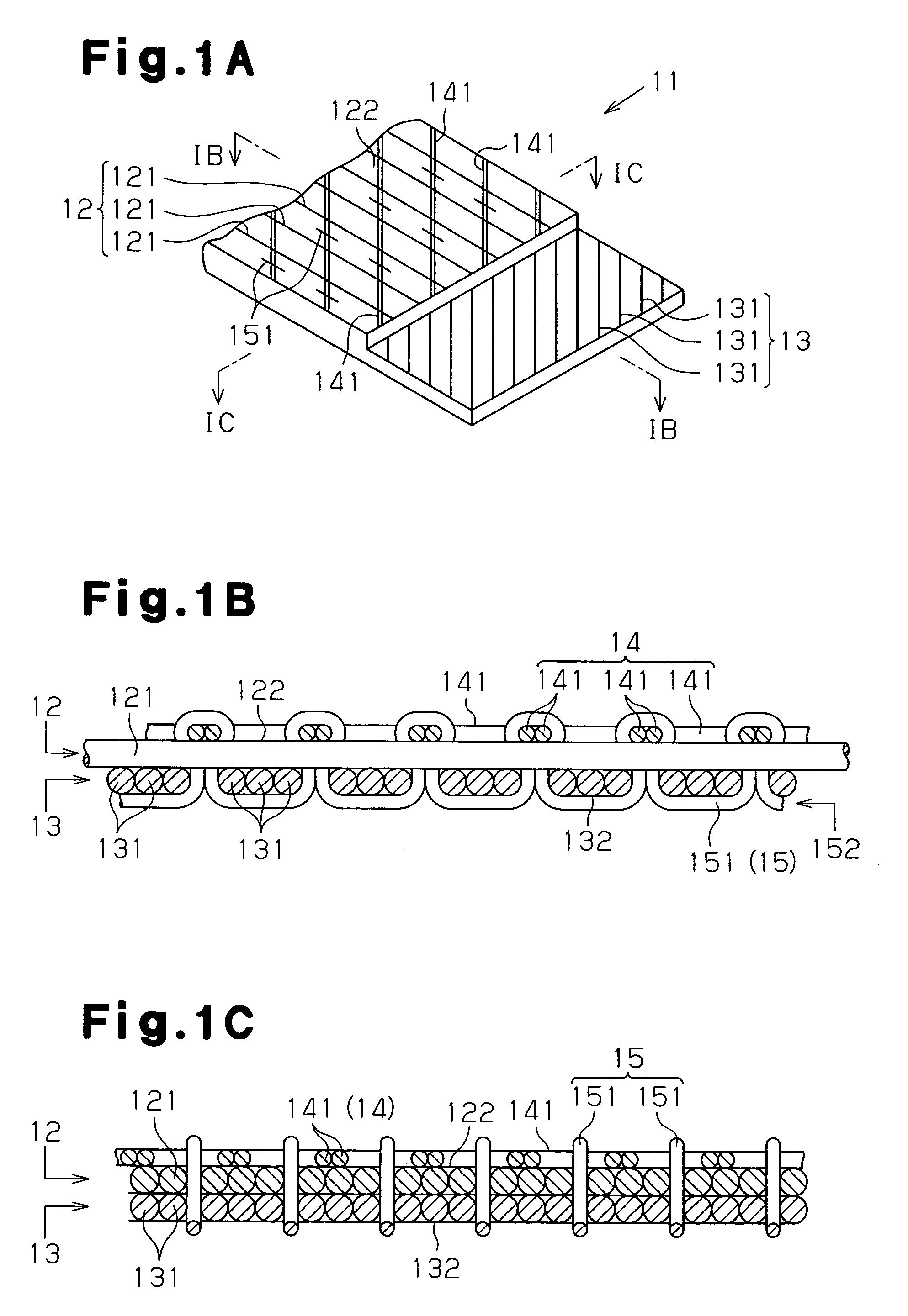
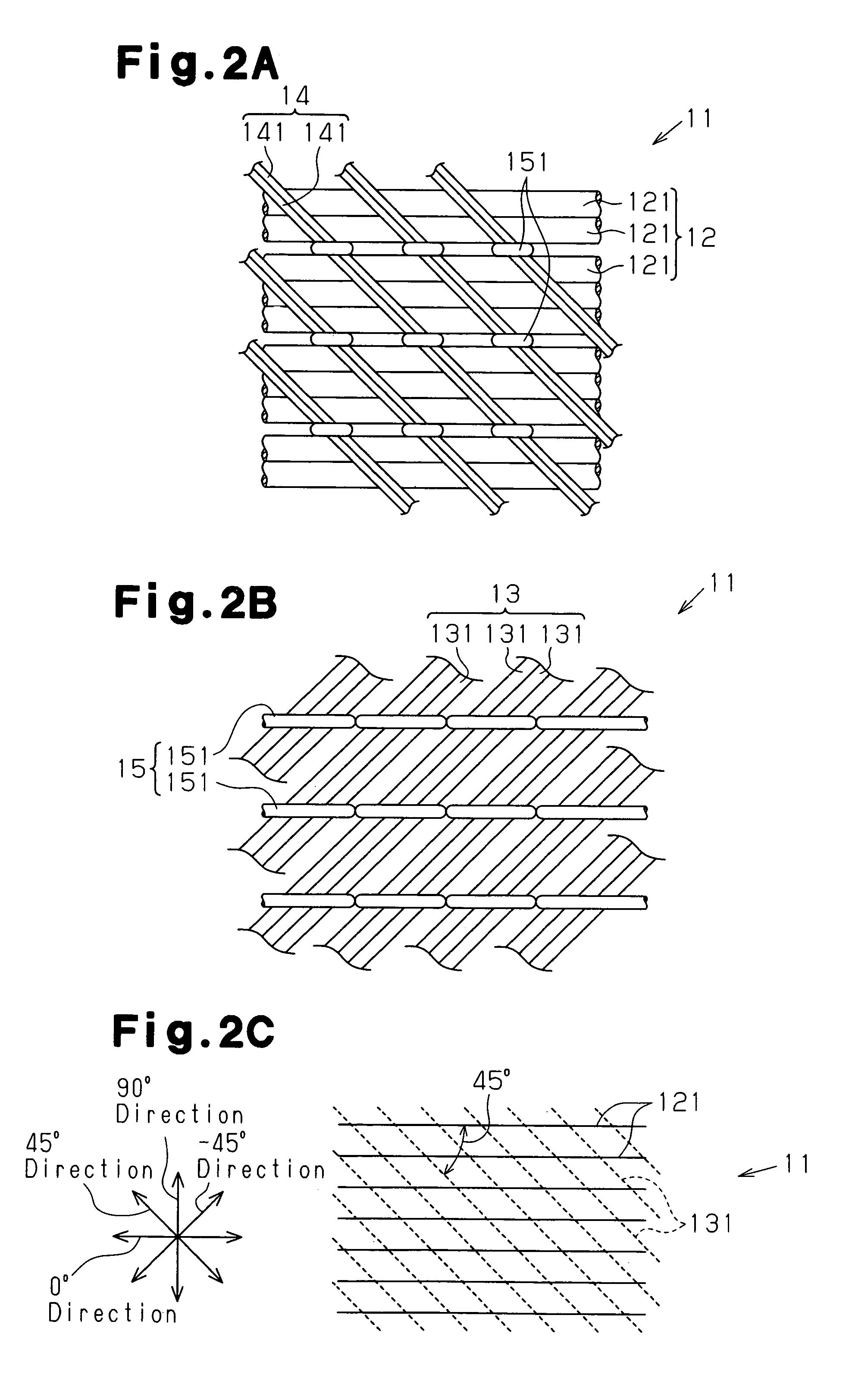
[0051]As shown in FIGS. 1A to 1C, a fiber fabric 11 is structured by a first fiber layer 12 formed of a plurality of first fiber bundles 121, a second fiber layer 13 formed of a plurality of second fiber bundles 131, a retaining thread group 14 formed of a plurality of retaining threads 141, and a constraint thread group 15 formed of a plurality of constraint threads 151. The first fiber layer 12 is laminated in adjacent to the second fiber layer 13. The constraint threads 151 extend in a thickness direction of the fiber fabric 11 and pass through the first fiber layer 12 and the second fiber layer 13. The retaining threads 141 intersect the constraint threads 151. An array pitch of the retaining threads 141 and the constraint threads 151 is set to be wider than an array pitch of the first fiber bundles 121 and the second fiber bundles 131. The threads in this ca...

second embodiment

[0082]As shown in FIG. 10A, the structure may be made such that the length direction of the constraint threads 151 is the. −45 degree direction. The length directions of the first fiber bundles 121, the second fiber bundles 131 and the retaining threads 141 constituting the fiber fabric 11E are the same as the case of the FIG. 10B shows a mirror fiber fabric 11EM having a mirror symmetrical relation to the fiber fabric 11E.

third embodiment

[0083]As shown in FIG. 11A, the structure may be made such that the length direction of the constraint threads 151 is the −45 degree direction. The length directions of the first fiber bundles 121, the second fiber bundles 131 and the retaining threads 141 constituting the fiber fabric 11F are the same as the case of the FIG. 11B shows a mirror fiber fabric 11FM having a mirror symmetrical relation to the fiber fabric 11D.


PUM

PropertyMeasurementUnit
angleaaaaaaaaaa
angleaaaaaaaaaa
angleaaaaaaaaaa

Abstract

A fiber fabric includes a first fiber layer formed of a plurality of first fiber bundles, a second fiber layer formed of a plurality of second fiber bundles, a retaining thread group formed of a plurality of retaining threads, and a constraint thread group formed of a plurality of constraint threads. The first fiber layer is laminated in adjacent to the second fiber layer. The first fiber bundles diagonally intersect the second fiber bundles at an angle of 45 degrees. Accordingly, it is possible to improve a production efficiency of an overlapped sheet which gives excellent moldability and a strength, and has an increased thickness by overlapping the fiber fabrics.

Description

BACKGROUND OF THE INVENTION[0001]The present invention relates to a fiber fabric and a composite material obtained by reinforcing a resin by the fiber fabric.[0002]A load energy absorbing member constructing a bumper apparatus cushioning an impact at a collision of a vehicle absorbs the energy of an impact load applied to a bumper reinforcement constructing the bumper apparatus. In order to save weight of the bumper apparatus, there has been known a composite material in which the bumper reinforcement or the load energy absorbing member is formed by a fiber reinforced resin.[0003]As the fiber for reinforcing the resin, for example, fabrics disclosed in the following publication can be employed.[0004]A fabric disclosed in Japanese Laid-Open Patent Publication No. 63-303145 is structured such that the weft is diagonally woven in the warp. However, since the fabric is woven only by the warp and the weft, threads are bent and meander, and it is disadvantageous in view of improving the s...

Claims


Application Information

Patent Timeline
Patent Type & Authority Patents(United States)
IPC IPC(8): B32B3/06B32B5/12B29B15/08B29K105/08B32B5/26B32B5/28D03D1/00D03D25/00D06M17/00
CPCB32B5/024B32B5/26D03D11/00D03D13/00F16F7/124D03D13/002B32B5/12Y10T428/24107B32B2250/02B32B2250/20B32B2262/0276B32B2262/101B32B2605/00B60R2019/1853D10B2505/02F16F2234/06Y10T428/24074Y10T428/24041Y10T428/24058Y10T428/24116Y10T428/24124Y10T442/3195
Inventor KAMIYA, RYUTA
Owner TOYOTA IND CORP
Why Eureka
Try Eureka