
Power-up signal generating circuit and method for driving the same

a power-up signal and signal generation technology, applied in the direction of pulse technique, instant pulse delivery arrangement, instruments, etc., can solve the problems of increasing initialization time, increasing current consumption, and unstable external voltage vdd level

Active Publication Date: 2010-03-09
SK HYNIX INC
View PDF7 Cites 38 Cited by
  • Summary
  • Abstract
  • Description
  • Claims
  • Application Information

AI Technical Summary

Problems solved by technology

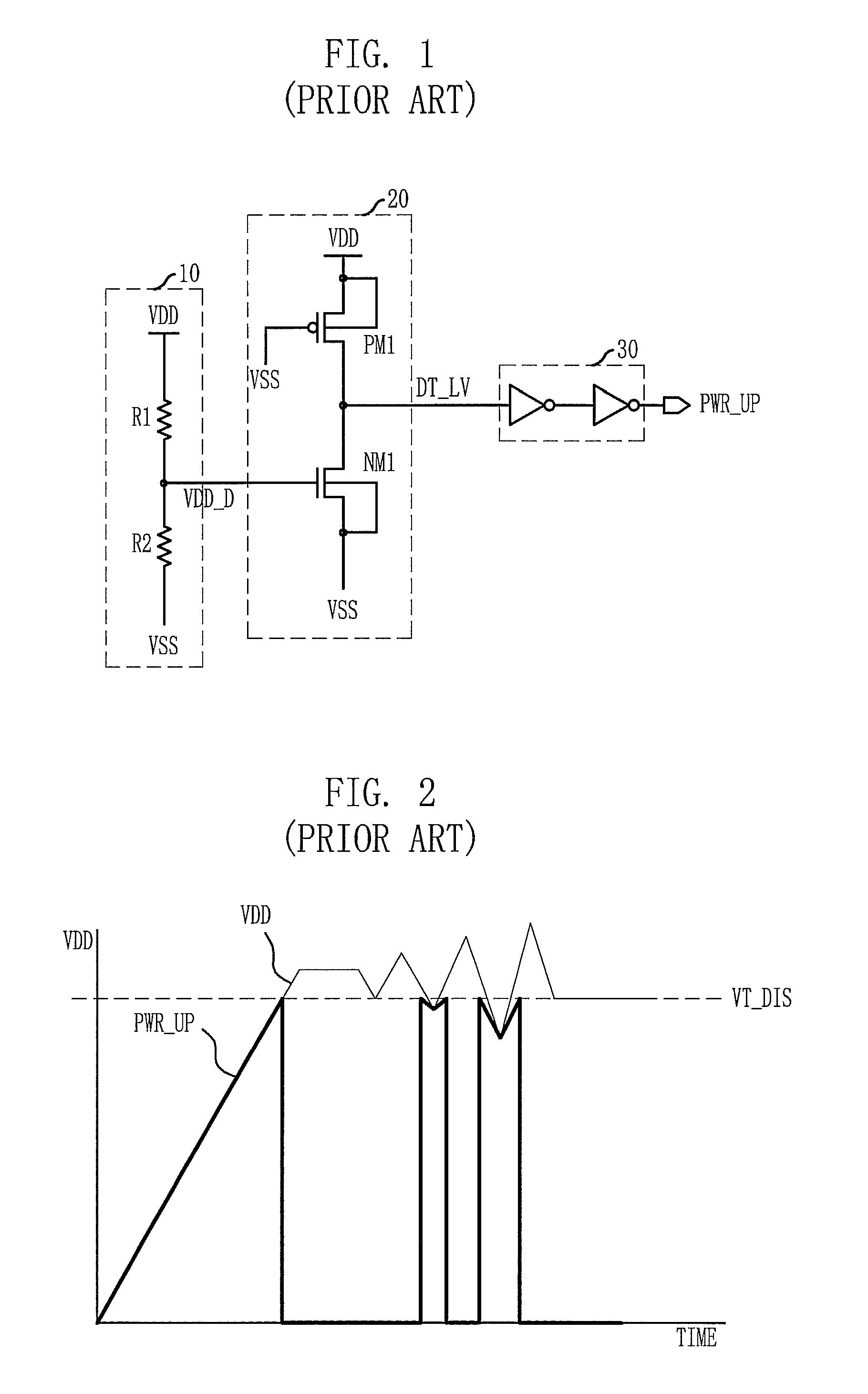
However, when the external voltage VDD is consumed by the internal blocks of the semiconductor memory device, the level of the external voltage VDD may become unstable around the upper limit reference voltage VT_DIS.
When this occurs, the initialization time is increased and current consumption increases due to this undesired operation.

Method used


Image

  • Power-up signal generating circuit and method for driving the same
  • Power-up signal generating circuit and method for driving the same
  • Power-up signal generating circuit and method for driving the same

Examples


Embodiment Construction

[0032]Hereinafter, a power-up signal generating circuit in accordance with embodiments of the present invention will be described in detail with reference to the accompanying drawings.

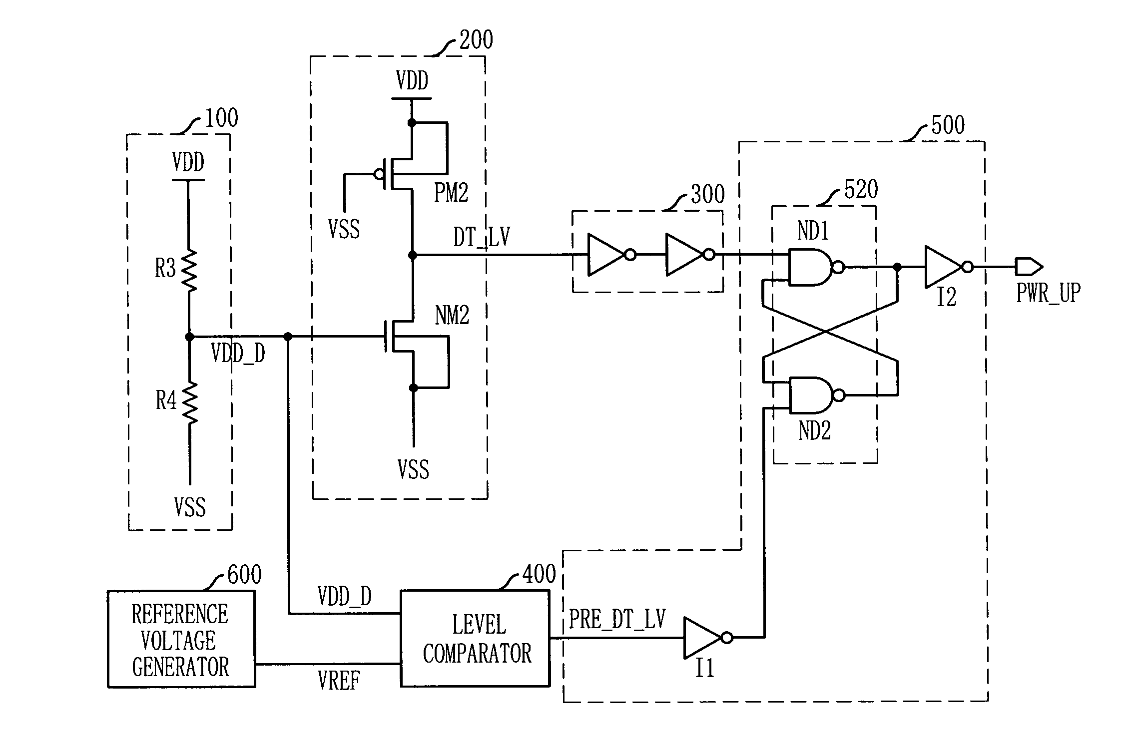
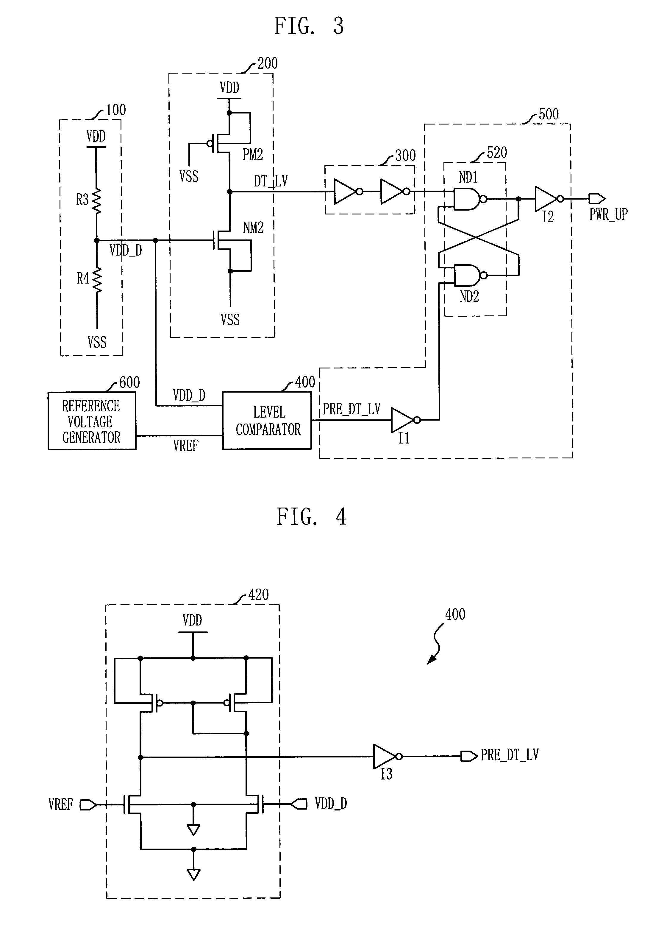
[0033]FIG. 3 is a schematic circuit diagram of a power-up signal generating circuit in accordance with an embodiment of the present invention.

[0034]Referring to FIG. 3, the power-up signal generating circuit includes a first pre-signal generating unit, a second pre-signal generating unit, and a main signal generating unit 500.

[0035]The first pre-signal generating unit deactivates a first level detection signal DT_LV when a level of an external voltage VDD increases above a upper limit reference voltage VT_DIS. The second pre-signal generating unit deactivates a second level detection signal PRE_DT_LV when the level of the external voltage VDD increases above a lower limit reference voltage VT_IIS. The main signal generating unit 500 activates a power-up signal PWR_UP to have the same level as the exter...


PUM


Abstract

A power-up signal generating circuit that prevents repeatedly generating a power-up signal even when there is noise on an external voltage. The power-up signal generating circuit includes a level detector, a level comparator, and a reentry protector. The level detector is configured to deactivate a first level detection signal when a level of an external voltage increases above a upper limit reference voltage. The level comparator is configured to deactivate a second level detection signal when the level of the external voltage increases above a lower limit reference voltage. The reentry protector is configured to activate the power-up signal in response to the second level detection signal and deactivate the power-up signal in response to a deactivation of the first level detection signal.

Description

CROSS-REFERENCE TO RELATED APPLICATIONS[0001]This application claims priority to Korean patent application number 10-2007-0032058, filed on Mar. 31, 2007, which is incorporated by reference in its entirety.BACKGROUND OF THE INVENTION[0002]The subject matter relates to a semiconductor memory device, and more particularly to a power-up signal generating circuit, which does not repeatedly activate a power-up signal when noise is applied to an external voltage, and a method for driving the same.[0003]As semiconductor memory technology has advanced, a core voltage applied to a cell has decreased. In some devices a power-up signal generating circuit is provided to generate a stable power-up signal at an initial operation after an external voltage is applied, even for device with differences in process, voltage, or temperature.[0004]The power-up signal generating circuit generates a power-up signal that is activated when a substrate bias voltage VBB reaches a desired level. The power-up si...

Claims


Application Information

Patent Timeline
Patent Type & Authority Patents(United States)
IPC IPC(8): H03K5/153
CPCH03K3/356008G11C5/147G11C11/4072G11C11/4074
Inventor JUNG, HO-DON
Owner SK HYNIX INC
Learn More