Internally shielded energy conditioner

a technology of energy conditioner and shielding, applied in the field of electrical technology, to achieve the effect of improving decoupling and high insertion loss

Inactive Publication Date: 2010-03-09
X2Y ATTENUATORS L L C
View PDF577 Cites 90 Cited by
  • Summary
  • Abstract
  • Description
  • Claims
  • Application Information

AI Technical Summary

Benefits of technology

[0017]An object of the invention is to provide a novel structure, a method of making the structure, and a method of using the structure, and related circuit configurations and their use, wherein the structure has a certain capacitance and provides energy conditioning that results in an ultra high insertion loss and improved decoupling.
[0030]The structure preferably has an electrically insulating material between the conductive layers or plates that thereby substantially prevents electrons from moving from one conductive layer through the insulating material to another conductive layer. The insulating material may be any material that has a dielectric constant. Examples of the insulating material are air, which has a dielectric constant of one, and material specified as X7R, which has a dielectric constant of about 4600, silicon, and semiconductors, and SiN and Diamond semiconductors. Preferably, the dielectric constant is relatively large in order to maximize capacitance per volume. However, the dielectric constant may be set at least in semiconductor applications by dielectric layers compatible with the semiconductor in question.

Problems solved by technology

However, for purposes of this application, the internal shield structure described below generally is not electrically connected to an external earth or chassis ground.

Method used


Image

  • Internally shielded energy conditioner
  • Internally shielded energy conditioner
  • Internally shielded energy conditioner

Examples


Embodiment Construction

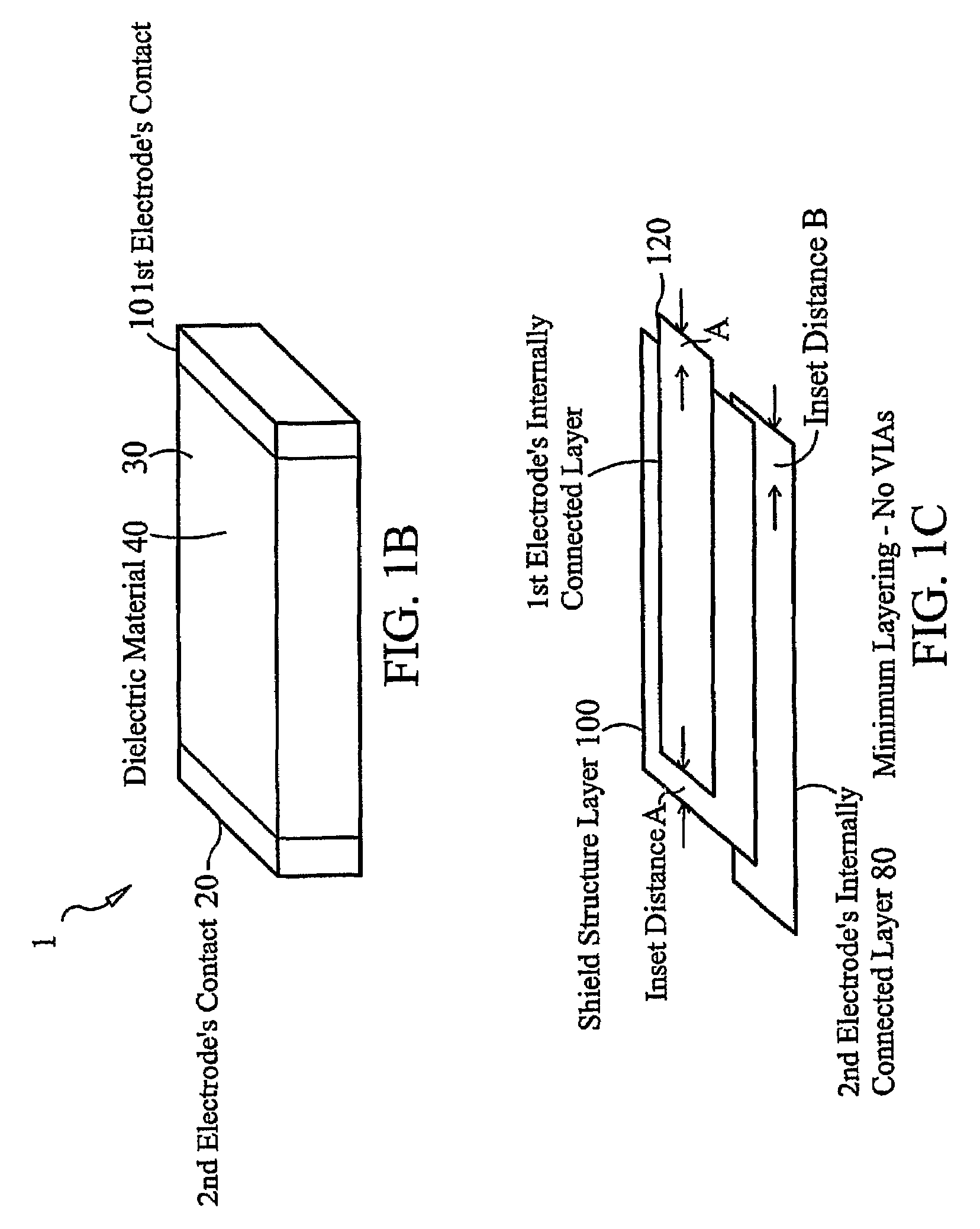
[0093]FIG. 1B shows an energy conditioning structure 1 including a first electrode contact 10, a second electrode contact 20, and a central region 30. The central region 30 has surfaces formed from one or more dielectric materials 40. The surfaces of the first electrode contact, the second electrode contact, and the dielectric material preferably define the entirety of the surface of the energy conditioning structure.

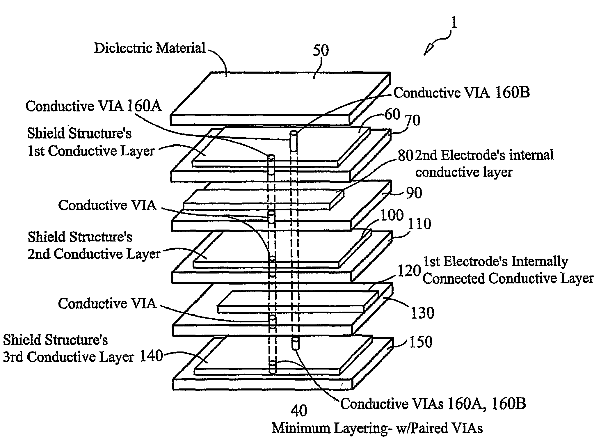
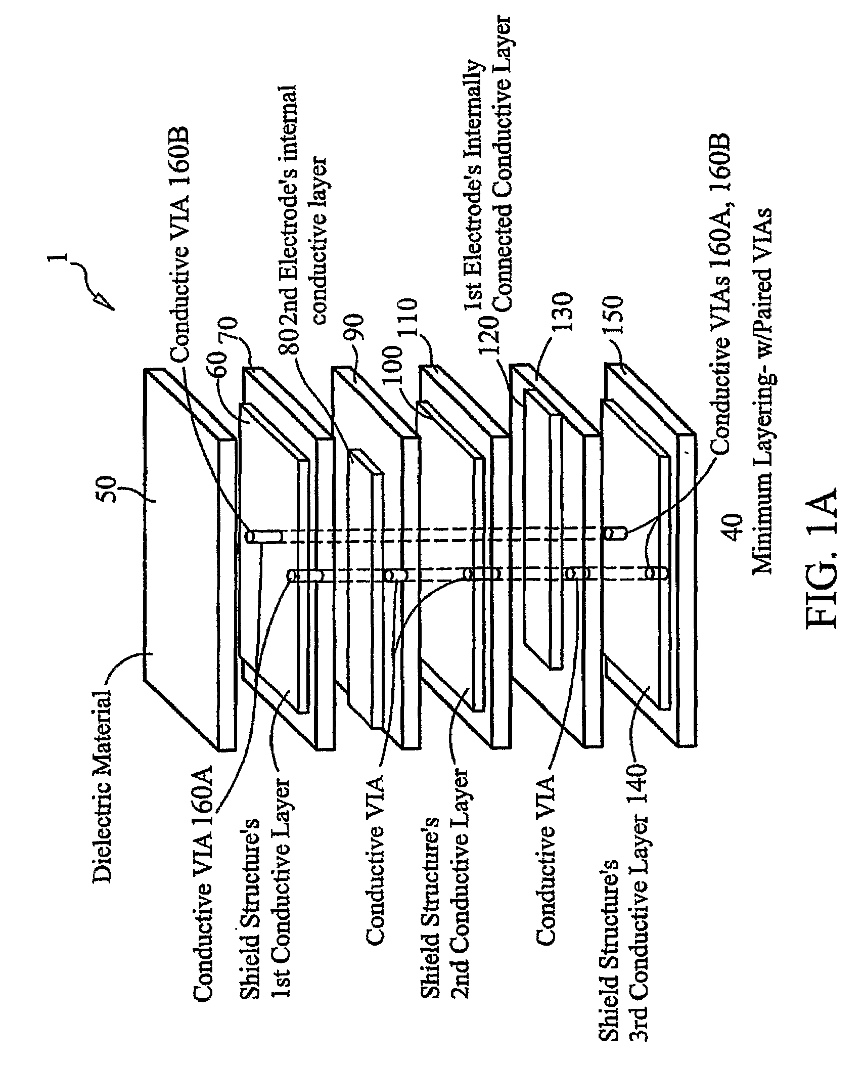
[0094]FIG. 1A shows a sequence of layers internal to energy conditioning structure 1. FIG. 1A shows the sequence of layers from top to bottom being dielectric material layer 50, shield structure first conductive layer 60, dielectric material layer 70, second electrode's internal conductive layer 80, dielectric material layer 90, shield structure's second conductive layer 100, dielectric material layer 110, first electrode's internally connected conductive layer 120, dielectric material layer 130, shield structure's third conductive layer 140, and dielectric material lay...


PUM


Abstract

An energy conditioner structure comprising a first electrode (120), a second electrode (80), and a shield structure (70, 110, 150) provides improved energy conditioning in electrical circuits. The structures may exist as discrete components or part of an integrated circuit. The shield structure in the energy conditioner structure does not electrically connect to any circuit element.

Description

CROSS REFERENCE TO RELATED APPLICATIONS[0001]This application is a U.S. national stage entry of international application PCT / US04 / 39777 filed Dec. 22, 2004, which claims priority to U.S. provisional application 60 / 530,987, filed Dec. 22, 2003, and the contents of that application is incorporated herein by reference.BACKGROUND OF THE INVENTION[0002]This invention relates to electrical technology. More specifically, this invention relates to low inductance devices and energy conditioning.DISCUSSION OF THE BACKGROUND[0003]The word “terminal” means electrically conductive material at the point at which current enters or leaves an electrical device.[0004]The terms “X” capacitor and “line to line capacitor” both mean a two terminal passive lumped circuit element having a capacitance value across the two terminals wherein the two terminals are connected in parallel configuration with a circuit load device. X capacitors are primarily used to prevent electrical droop across loads. That is, ...

Claims


Application Information

Patent Timeline
Patent Type & Authority Patents(United States)
IPC IPC(8): H02H9/00H05K1/02
CPCH01G4/35H01L23/552H01P1/203H05K1/0233H01L2924/0002H01L2924/3011H05K2201/09254H05K2201/0969H05K2201/09772H05K2201/09781H05K2201/1006H05K2201/10454H05K2201/10636H01L2924/00Y02P70/50H02H9/02H05K9/00
Inventor ANTHONY, DAVIDANTHONY, ANTHONYANTHONY, WILLIAM M.MUCCIOLI, JAMESNEIFELD, RICHARD A.
Owner X2Y ATTENUATORS L L C
Why Eureka
Try Eureka