Optical pickup with beam generating and focusing

a technology of optical pickup and optical disk, applied in the direction of optical recording head, data recording, instruments, etc., can solve the problems of large increase in the overall size of the apparatus, and complex apparatus structure, so as to prevent a reduction in light intensity and excellent recording and replay

Inactive Publication Date: 2010-03-09
SONY CORP
View PDF12 Cites 0 Cited by
  • Summary
  • Abstract
  • Description
  • Claims
  • Application Information

AI Technical Summary

Benefits of technology

[0013]An optical pickup and an optical disk apparatus according to an embodiment of the present invention uses the same objective lens corresponding to three different wavelengths and can maintain a predetermined working distance and prevent a reduction in the light intensity. In this way, the optical pickup and the optical disk apparatus carry out excellent recording and replay.
[0016]An optical pickup and an optical disk apparatus according to an embodiment of the present invention uses the same objective lens corresponding to three different wavelengths and can maintain a predetermined working distance and prevent a reduction in the light intensity. In this way, the optical pickup and the optical disk apparatus carry out excellent recording and replay on a plurality of different types of optical disks having three different usable wavelengths.

Problems solved by technology

Therefore, the overall size of the apparatus is great, and the structure of the apparatus becomes complex.
Thus, there is a problem in that the overall size of the apparatus increases.
However, due a reduction in the light intensity caused by the diffraction efficiency and transmittance of the optical element, it has been extremely difficult to carry out excellent recording and replay for an optical disk using three different wavelengths.

Method used


Image

  • Optical pickup with beam generating and focusing
  • Optical pickup with beam generating and focusing
  • Optical pickup with beam generating and focusing

Examples


example

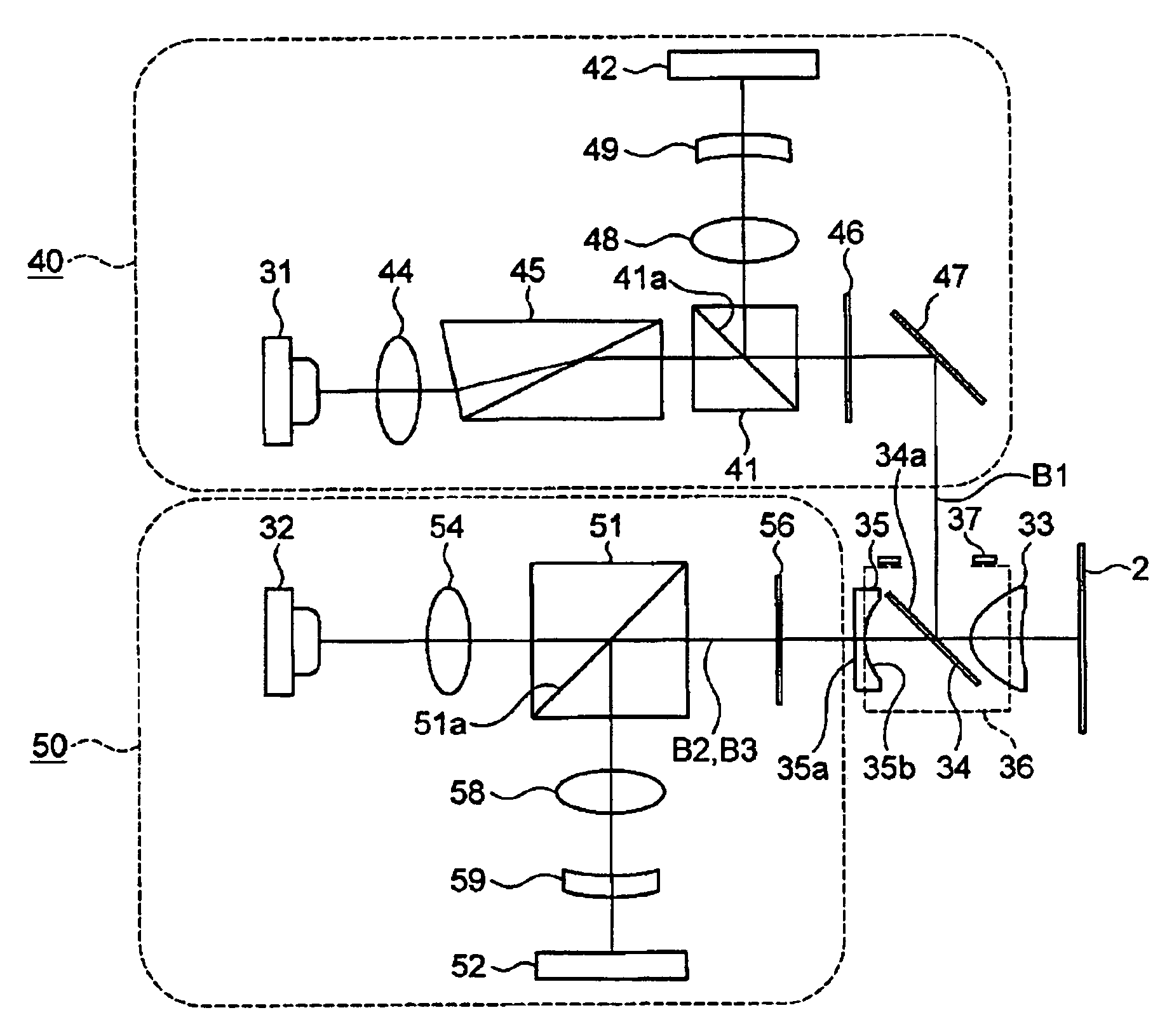
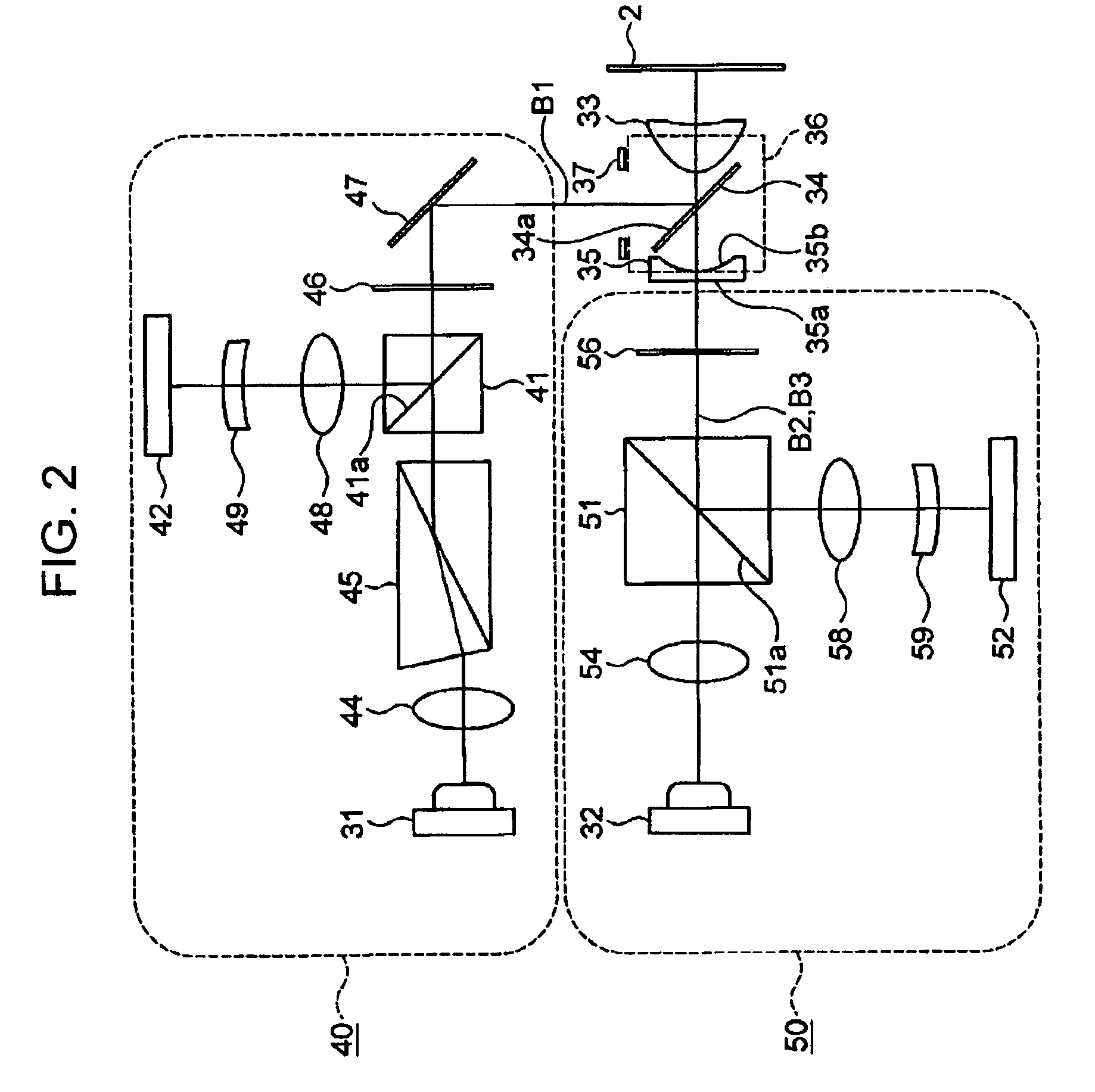
[0110]The objective lens 33 and the aberration correcting unit 35 included in the optical pickup 3 according to an embodiment of the present invention will be described in detail below with reference to FIGS. 6 and 7 and the numerical data shown in Tables 1 to 3.

[0111]Table 1 shows the aspherical coefficients representing the aspherical shape of the first surface S1 of the objective lens 33 on the optical-path combining unit 34 side and the second surface S2 on the optical disk side, as shown in FIG. 6, and represents various conditions corresponding to the above-described Expression 1.

[0112]

TABLE 1S1S2r1.337376.48654k−0.38627−16.5297A−3.5645E−03−4.6689E−02B2.6174E−033.5462E−01C−1.1319E−02−1.1835E+00D1.9685E−021.6808E+00E−1.6661E−02−5.7116E−01F3.1738E−03−1.2688E+00G2.6161E−031.7314E+00H−1.4267E−03−8.6942E−01J1.9881E−041.6234E−01

[0113]The index of refraction N2 of the objective lens 33 differs depending on the wavelength; the index of refraction N21 for the first wavelength (405 nm) ...


PUM

PropertyMeasurementUnit
first wavelengthaaaaaaaaaa
second wavelengthaaaaaaaaaa
third wavelengthaaaaaaaaaa

Abstract

An optical disk apparatus includes an optical pickup and a disk-rotation driving unit configured to rotationally drive the optical disks. The optical pickup includes a first emission unit configured to emit a first wavelength beam; a second emission unit configured to emit a second wavelength beam; a third emission unit configured to emit a third wavelength beam; an objective lens configured to focus the first to third wavelength beams emitted from the first to third emission units, respectively, at a signal recording surface of an optical disk; a light-path combining unit configured to combine an optical path of the first wavelength beam emitted from the first emission unit and an optical path of the second and third wavelength beams emitted from the second and third emission units, respectively; and an aberration correcting unit provided on the optical path of the second and third wavelength beams.

Description

CROSS REFERENCES TO RELATED APPLICATIONS[0001]The present invention contains subject matter related to Japanese Patent Application JP 2006-107952 filed in the Japanese Patent Office on Apr. 10, 2006, the entire contents of which are incorporated herein by reference.BACKGROUND OF THE INVENTION[0002]1. Field of the Invention[0003]The present invention relates to an optical pickup and an optical disk apparatus including an optical pickup that are capable of recording and replaying information signals using one objective lens for three different types of disk recording medium.[0004]2. Description of the Related Art[0005]As next-generation optical disk format, a known optical disk capable of high-density recording (hereinafter referred to as a high-density recording optical disk) in which recording and replay of a signal is carried out using an optical beam having a wavelength of approximately 405 nm generated by a blue-violet semiconductor laser has been proposed. As such a high-density...

Claims


Application Information

Patent Timeline
Patent Type & Authority Patents(United States)
IPC IPC(8): G11B7/00
CPCG11B7/1353G11B2007/0006
Inventor HINENO, SATOSHI
Owner SONY CORP
Why Eureka
Try Eureka