
Determining client latencies over a network

a network and client technology, applied in the field of determining client latencies over networks, can solve problems such as user's abandonment of web site visits, client latency, poor performance,

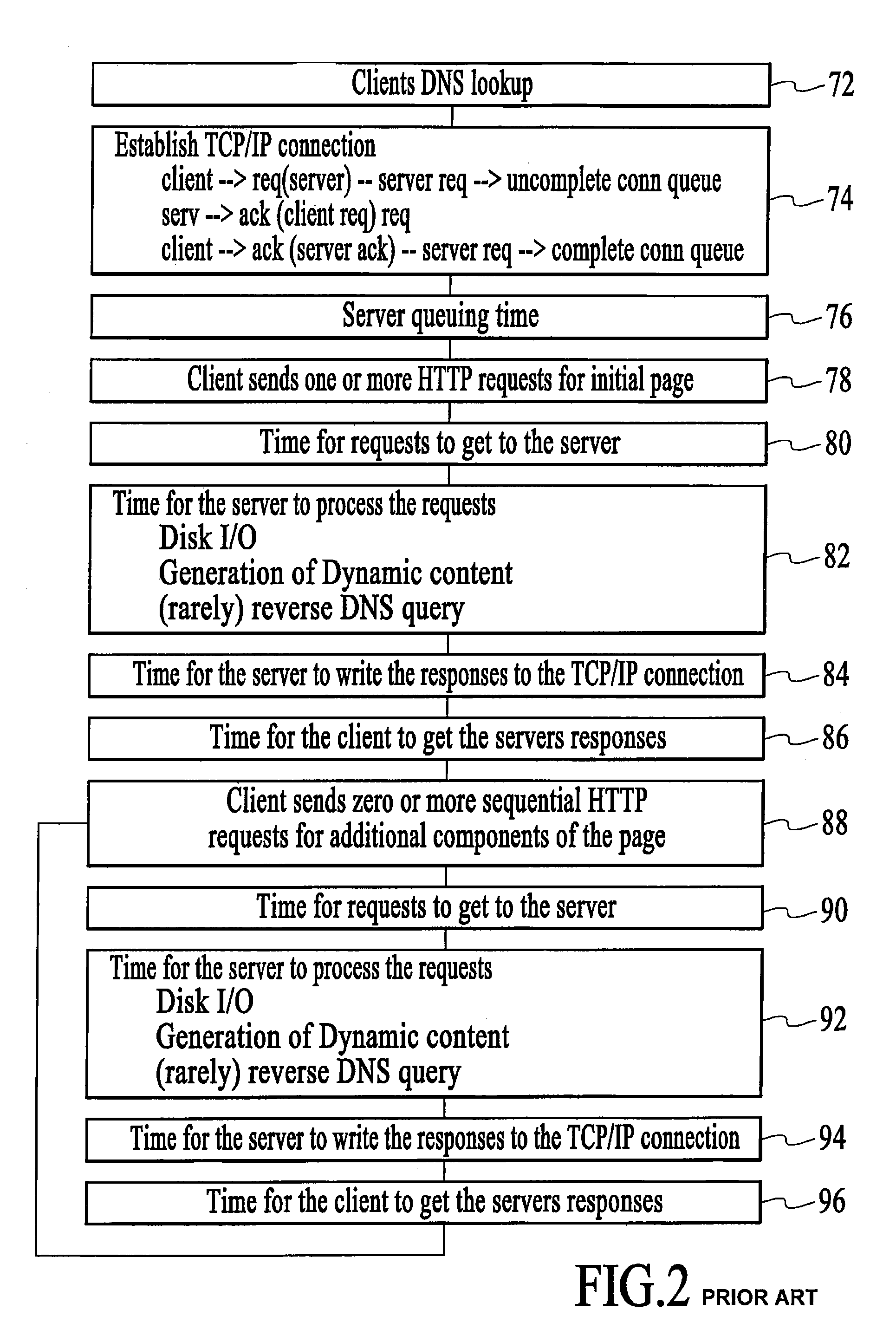
Inactive Publication Date: 2010-03-09
ZARBANA DIGITAL FUND
View PDF32 Cites 331 Cited by
  • Summary
  • Abstract
  • Description
  • Claims
  • Application Information

AI Technical Summary

Benefits of technology

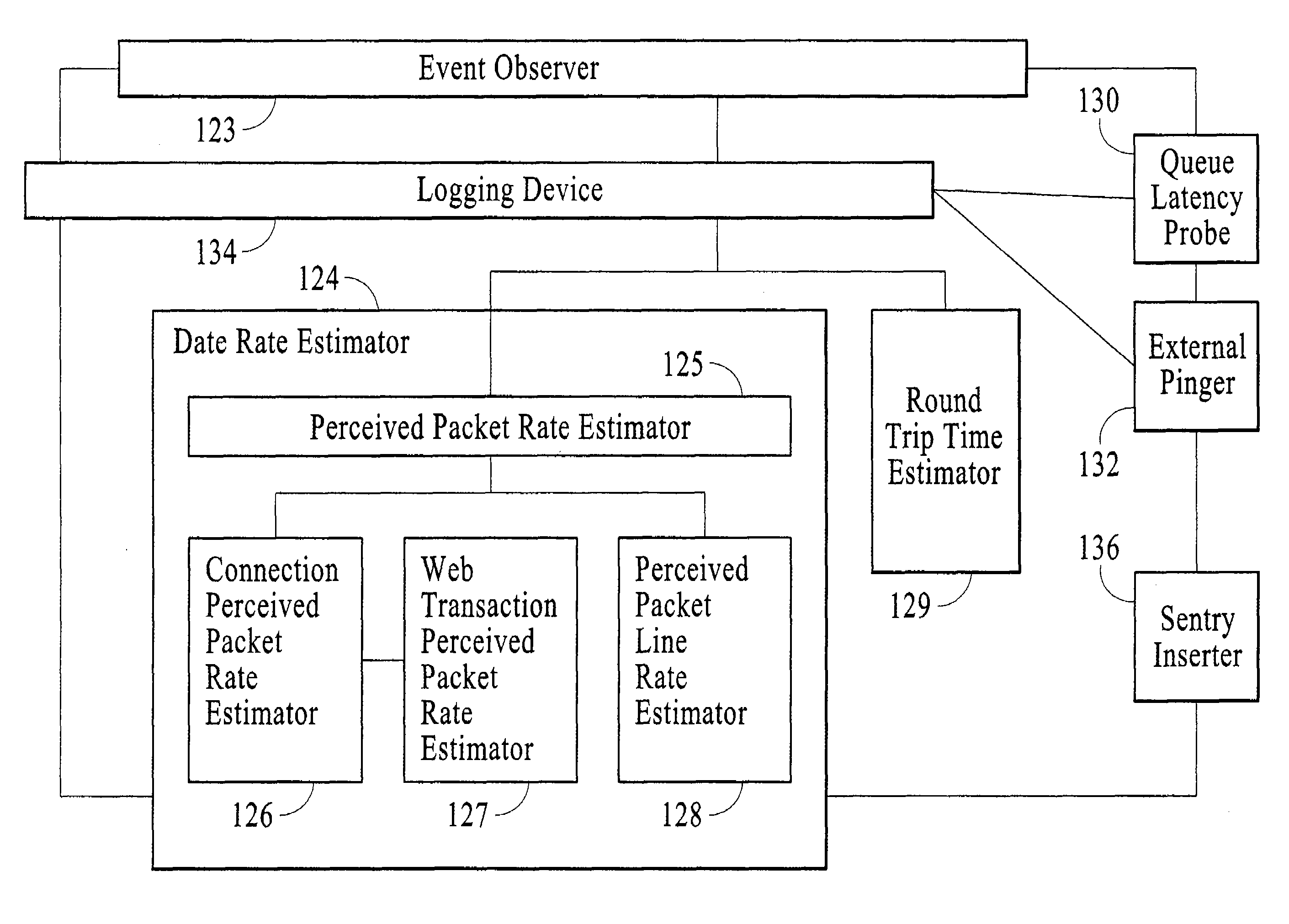
"The present invention provides a network latency estimation apparatus for estimating the time it takes for a client to receive a server's response to a request for data. The apparatus includes an event observer for observing pre-selected events associated with the communication, a logging device for logging the observed events and their time information, and a latency estimator for using the recorded events and time information to estimate the client's latency. The apparatus can also include a pinger for sending out a ping and a round-trip-time estimator for estimating the round-trip time between the server and the client. The apparatus can also include a queuing latency probe for sending a queue probing request to the server and a transmission-data-rate estimator for estimating the data rate between the server and the client. The technical effect of the invention is to provide a more accurate way of estimating the time it takes for a client to receive a server's response to a request for data, which can be useful in improving network communication speed and efficiency."

Problems solved by technology

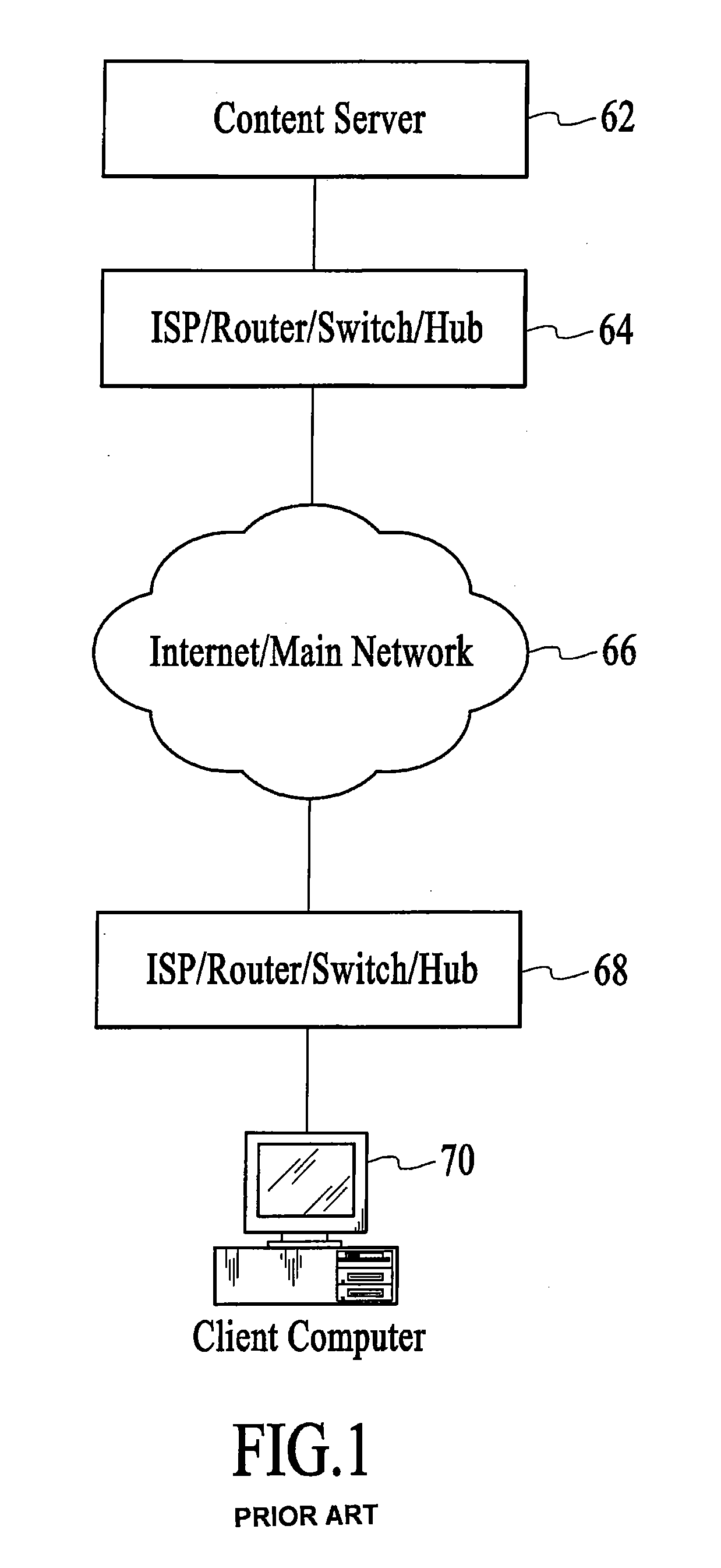
A central performance problem in the World Wide Web, in recent years, has been client latency.
Impatience with poor performance is the most common reason a user's visit to a web sites is abandoned.
For e-commerce sites, these abandonments translate into lost revenue.
(1) The server is dependent upon an external body for conducting the measurements,
(2) The agent's measurements do not necessarily reflect actual client experience,
(3)The perceived latency measured by the agents does not have a breakdown of the various latency components, and
(4)The agents' DNS lookup time is effected by prior DNS lookup queries.
Using a new TCP connection for each request led to incurring connection-establishment latencies on each request.

Method used


Image

  • Determining client latencies over a network
  • Determining client latencies over a network
  • Determining client latencies over a network

Examples


examples

[0368]Reference is now made to FIG. 13, which is a simplified schematic of an architecture used to test a preferred embodiment of the invention. In FIG. 13 there is a web-server 310, which is connected to a LAN 326. The LAN has four computers, 312, 314, 316, 318, which serve to send requests to the web-server. These requests may simulate various loads on the web server. The LAN is connected to a WAN, and the Internet 324, which is connected to two web-client simulators, 320, and 322, located at various distances from the server.

[0369]The server side latency estimator was implemented on an Apache web-server 310, running version 1.3.9, a public domain HTTP / 1.1 server. Measurements were conducted at three locations, namely at the web server, referred to as TAU, 310, and at both clients 320, and 322. One web client, called MTA 320, was located relatively close to the server, and one, called UCI, 322 client, was located relatively far from the server.

[0370]In order to make an evaluation ...


PUM


Abstract

A network latency estimation apparatus for estimating latency in network communications between a server and a client. The apparatus comprises an event observer for observing occurrences of pre-selected events. The events associated with the communication occurring at the server. A logging device associated with the event observer for logging into a data store the occurrence of the events together with respective time information. A latency estimator associated with the logging device for using the logged occurrences with the respective time information to arrive at an estimation of a client's latency for the communication.

Description

CROSS-REFERENCE TO RELATED APPLICATIONS[0001]This application is a continuation of U.S. pat. application Ser. No. 10 / 170,460 filed Jun. 14, 2002, entitled “Determining Client Latencies Over A Network” which is hereby expressly incorporated by reference for all purposes.FIELD OF THE INVENTION[0002]The present invention relates to determining client latencies over networks, particularly during the course of downloading procedures, and more particularly but not exclusively to determining client latencies in downloads of web pages over the Internet.BACKGROUND OF THE INVENTION[0003]A central performance problem in the World Wide Web, in recent years, has been client latency. Client latency may be defined as the time a client has to wait, between requesting data from a server, and finishing to download the requested data, and all data associated with the request.[0004]Impatience with poor performance is the most common reason a user's visit to a web sites is abandoned. For e-commerce site...

Claims


Application Information

Patent Timeline
Patent Type & Authority Patents(United States)
IPC IPC(8): G06F15/173H04L29/06
CPCH04L43/0852H04L43/0864H04L43/0888H04L69/16H04L69/28H04L69/163H04L43/10
Inventor LEVY, HANOCHMARSHAK, MARIK
Owner ZARBANA DIGITAL FUND
Learn More