Method for operating a vacuum handling device

a technology of handling device and vacuum, which is applied in the direction of ripping head, instruments, applications, etc., can solve the problems of gradually dropping vacuum provided therein, and achieve the effect of saving vacuum

Active Publication Date: 2010-03-16
J SCHMALZ GMBH
View PDF11 Cites 80 Cited by
  • Summary
  • Abstract
  • Description
  • Claims
  • Application Information

AI Technical Summary

Benefits of technology

[0012]The vacuum generator has a pressure sensor (second pressure sensor) for measuring the underpressure between the vacuum generator and the control valve. When this vacuum reaches a limit value (fourth limit value) which can, in particular, be adjusted, the vacuum generator is switched off. This fourth limit value is e.g. 750 mbar. A further limit value (third limit value) is stored in the programmable controller, which is e.g. 650 mbar. When the system between the vacuum generator and the control valve leaks, the vacuum provided therein gradually drops. When the vacuum reaches the third limit value, the vacuum generator is automatically switched on again, and the underpressure is increased until the fourth limit value is reached. The switching frequency of the vacuum generator thus monitors the tightness of the vacuum system between the vacuum generator and the control valve.
[0014]The desired vacuum is advantageously applied in the overall system up to the control valve in the gripper module. When the object is gripped, the vacuum line between the vacuum generator and the gripper module must no longer be evacuated. The system therefore provides for vacuum storage. For this reason, the workpiece can be suctioned more quickly.
[0015]When the programmable controller receives the command for the second switching state (pick up), the control valve in the gripper module is opened. The gripper module itself is very quickly evacuated, since the space to be evacuated is relatively small. The object is thus suctioned and gripped very quickly. As soon as the desired vacuum in the gripper module has been obtained, the control valve is closed. The first pressure sensor monitors the underpressure in the gripper module, thereby determining the tightness of the gripper module. When the gripper module leaks, e.g. due to a worn sealing lip, the underpressure in the gripper module drops relatively quickly, such that the control valve must be reopened when the underpressure falls below a fourth limit value in order to restore the desired underpressure. The switching frequency of the control valve is monitored by the programmable controller, thereby determining the tightness of the gripper module. It is thereby possible to detect those gripper modules which already show a certain untightness due to wear and will fail in the near future.
[0016]The underpressure in the gripper module can be quickly established, since the underpressure provided by the vacuum generator is applied up to the control valve. When this underpressure reaches its lower limit value, the vacuum generator is switched on again, as mentioned above, and the underpressure in the system is raised.
[0017]When the gripper module is not applied to the workpiece, no underpressure can be generated, since the gripper module suctions air from the surroundings. This is immediately detected by the pressure sensor, and the control valve of this gripper module is closed to thereby save vacuum.

Problems solved by technology

When the system between the vacuum generator and the control valve leaks, the vacuum provided therein gradually drops.

Method used


Image

  • Method for operating a vacuum handling device
  • Method for operating a vacuum handling device
  • Method for operating a vacuum handling device

Examples


Embodiment Construction

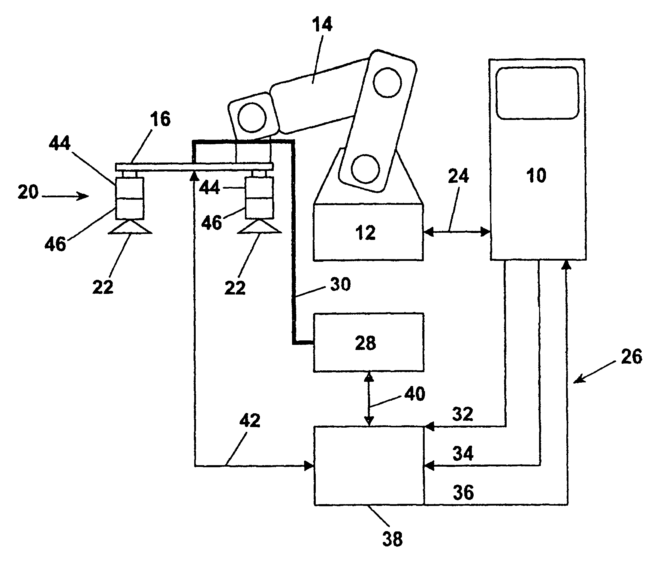
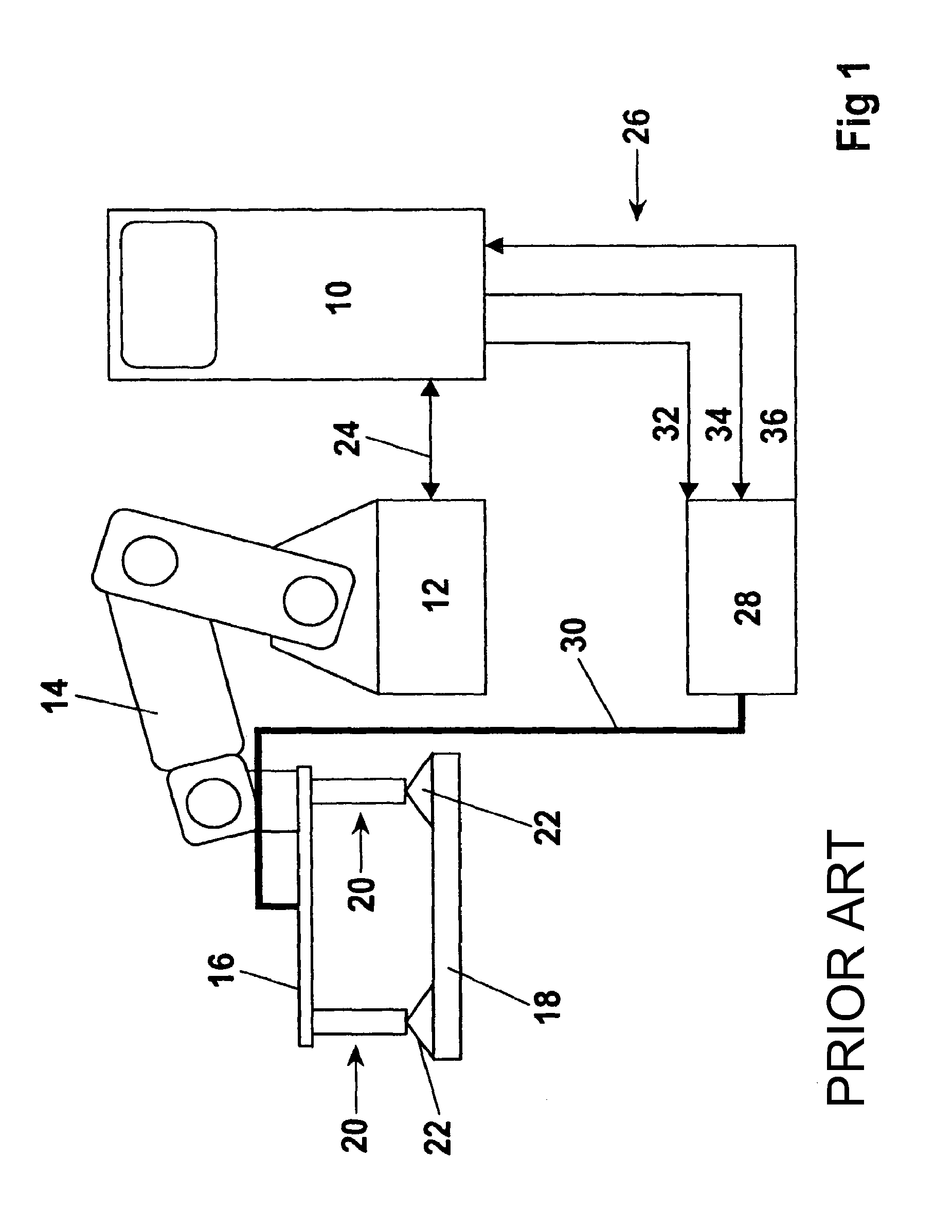
[0025]In FIG. 1, reference numeral 10 designates a machine controller for controlling a robot 12. A surface gripper, designated in total by 16, is flanged to the arm 14 of the robot 12, for gripping and transporting a workpiece 18. The surface gripper 16 has several gripper modules 20 which suction the workpiece 18 with one vacuum gripper 22 each. The machine controller 10 controls the robot 12 directly via a line 24 and controls a vacuum generator 28 via lines 26. The vacuum generator 28 is connected to the surface gripper 16 via a vacuum line 30. The vacuum generator 28 receives a command 32 (pick up) via the lines 26, for suctioning and lifting the workpiece 18, and a command 34 (release) for blowing-off and releasing the workpiece 18. The machine controller 10 moreover receives a command 36 from the vacuum generator 28 for the presence of vacuum. This construction corresponds to prior art, wherein the individual gripper modules 20 cannot be individually controlled.
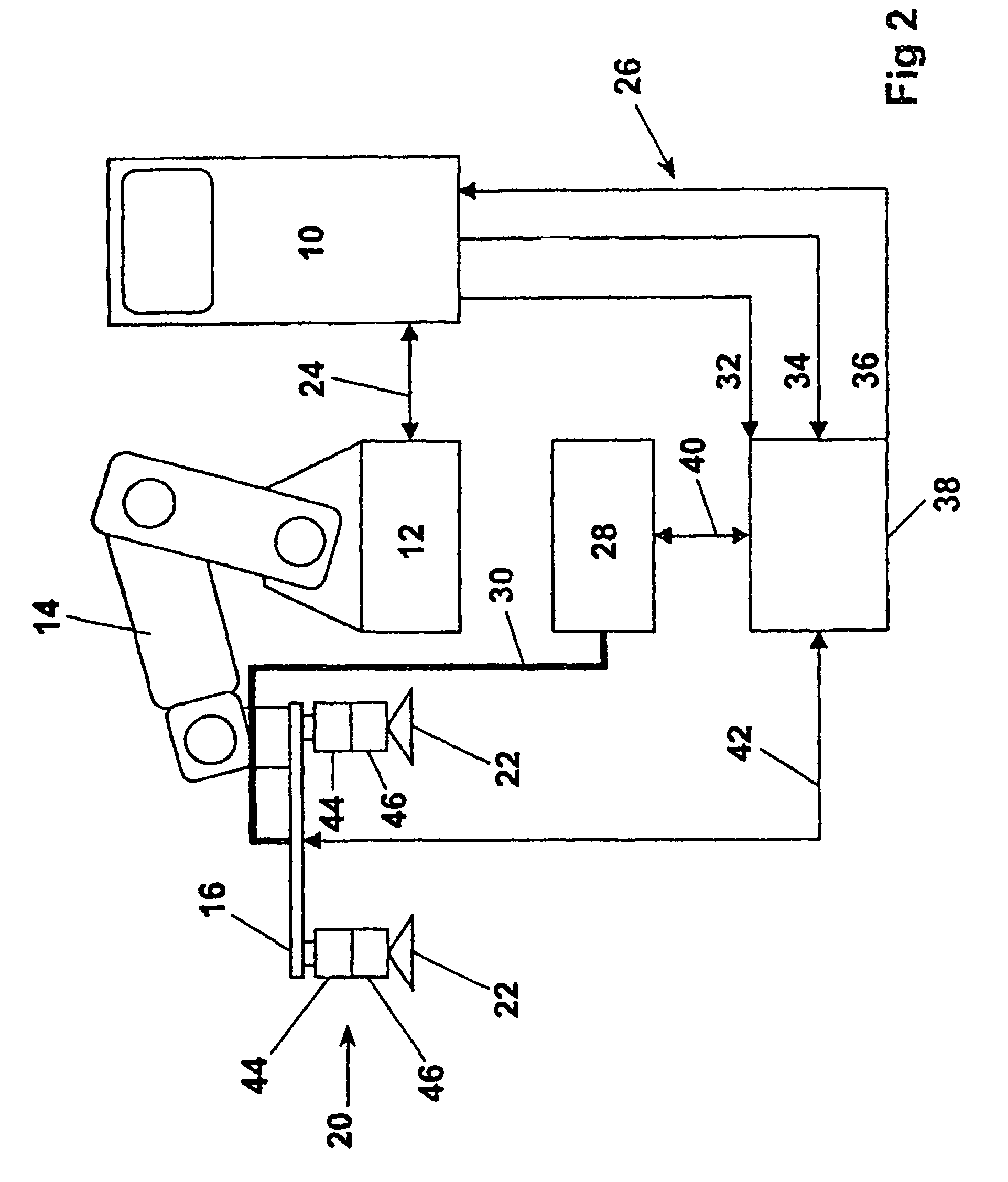
[0026]FIG. 2 s...


PUM


Abstract

A method is proposed for operating a vacuum handling device controlled by a programmable controller (39) which can be connected to a machine controller (10), with at least one vacuum generator (28) and with a number of gripper modules (20), which are connected to the vacuum generator and are each equipped with a first pressure sensor (46) and with a control valve (44) for the vacuum in the gripper module, and which are connected to the programmable controller. The control valve in the gripper module is closed in a first switching state (vacuum on) of the programmable controller and is detected up to the control valve (44) by means of a second pressure sensor (78) in the vacuum generator.

Description

[0001]This application is the national stage of PCT / EP2005 / 008011 filed on Jul. 22, 2005 and also claims Paris Convention priority of DE 10 2004 042 825.5 filed on Aug. 28, 2004.BACKGROUND OF THE INVENTION[0002]The invention concerns a method for operating a handling device Controlled by a programmable controller which can be connected to a Machine controller, with at least one vacuum generator and with a Number of gripper modules which are connected to the vacuum generator, Which are each equipped with a first pressure sensor and a control valve For the vacuum in the gripper module, and which are connected to the Programmable controller.[0003]A vacuum handling device generally consists of a vacuum generator, valve technology for controlling the vacuum, sensor technology for monitoring the vacuum, and at least one pneumatic gripper module. Systems of this type are used both for manual handling of unit loads and in automation technology.[0004]Especially in automation technology, each...

Claims


Application Information

Patent Timeline
Patent Type & Authority Patents(United States)
IPC IPC(8): B25J15/06B25J13/08
CPCB65G47/917B65G2201/022Y10S294/907
Inventor DUNKMANN, WALTERSCHMIERER, GERNOT
Owner J SCHMALZ GMBH
Why Eureka
Try Eureka