Protected connection interface for direct torque flow constant velocity joint and method thereof

a technology of connection interface and constant velocity joint, which is applied in the direction of mechanical equipment, manufacturing tools, couplings, etc., can solve the problems of additional potential corrosion of the connection interface with the drive unit, and achieve the effect of reducing the exposure of unwanted debris

Inactive Publication Date: 2010-03-16
GKN DRIVELINE NORTH AMERICA
View PDF11 Cites 30 Cited by
  • Summary
  • Abstract
  • Description
  • Claims
  • Application Information

AI Technical Summary

Benefits of technology

[0004]Accordingly, the present invention provides a protected connection interface for a direct torque flow constant velocity joint. The connection interface may minimize exposure from unwanted debris. Also, the connection interface may provide protection from corrosion.

Problems solved by technology

Moreover, because the boot does not extend across the connection interface with a DTF connection, there is the additional potential for corrosion in the connection interface with the drive unit.

Method used


Image

  • Protected connection interface for direct torque flow constant velocity joint and method thereof
  • Protected connection interface for direct torque flow constant velocity joint and method thereof
  • Protected connection interface for direct torque flow constant velocity joint and method thereof

Examples


first embodiment

[0025]While the invention is described for a particular DTF CVJ having balls and sets of ball tracks for a particular type of constant velocity joint motion, it is recognized that any other suitable constant velocity balls and sets of ball tracks may be utilized with the current invention. Moreover, the DTF CVJ may also be of the fixed or plunging type of joint as is recognized within the art. Because CVJ's are well understood to a person of skill in the art, the DTF CVJ's as given in each embodiment are discussed below only to the extent necessary to further describe the invention.

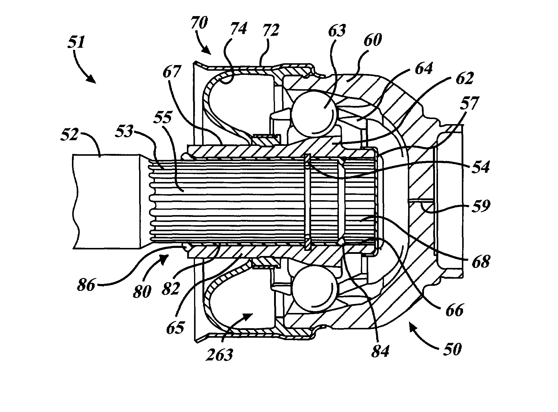
[0026]FIG. 2 shows a cross-sectional view of a first embodiment of an inventive protected connection interface 80 being used to advantage with a DTF CVJ connection 51. The connection 51 includes a DTF CVJ connector 50 coupled to a shaft 52 of a drive unit. The DTF CVJ 50 includes splines 68 located on the inner bore 66 of the unitary inner joint part 62 for securing to the splines 53 located on the outer ...

second embodiment

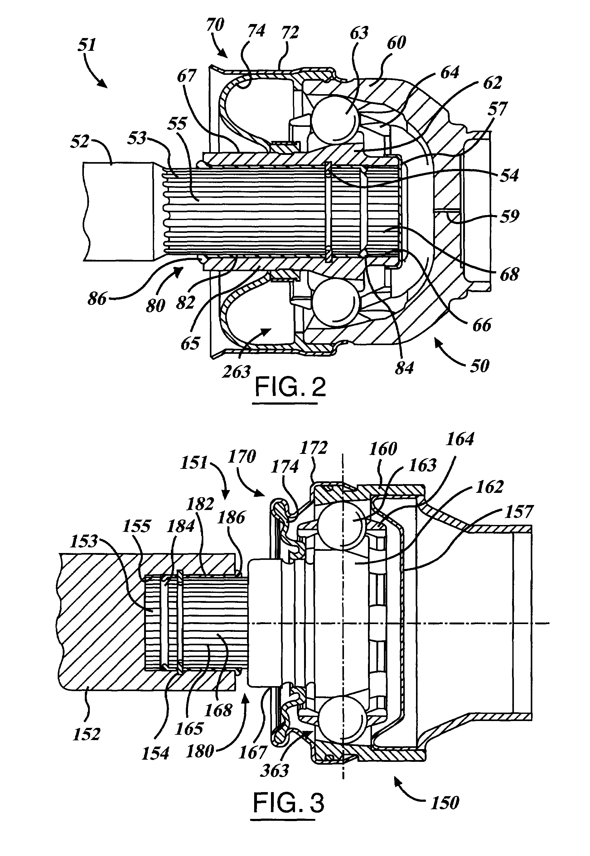
[0030]FIG. 3 shows a cross-sectional view of an inventive protected connection interface 180 being used to advantage with a DTF CVJ connection 151. The connection 151 includes a DTF CVJ connector 150 coupled to a shaft 152 of a drive unit. The unitary inner joint part 162 of the DTF CVJ 150 further includes an axial extension 165 axially extending outwardly from the unitary inner joint part 162. The DTF CVJ 150 includes splines 168 located on the outer surface 167 of the extension 165 of the unitary inner joint part 162 for securing to the splines 153 located on the inner bore 155 of a shaft 152 of a drive unit in a rotationally fast way. The splines 168 and 153 may be of any type or form and are well understood to a person of skill in the art. A sealant 182 is fully coated between the outer surface 167 of the unitary inner joint part 162 and the inner bore 155 of the shaft 152, thereby providing protection from debris and ingress of unwanted liquid such as water. Optionally, the se...


PUM


Abstract

A direct torque flow constant velocity joint connection interface includes a drive unit, a direct torque flow constant velocity joint connector and a sealant. The drive unit includes a shaft having a second interface surface. The direct torque flow constant velocity joint connector includes a unitary inner joint part having a first interface surface, where the first interface surface is connected to the second interface surface of the drive unit. The sealant provides filling between the first and second interface surfaces. Also provided is a direct torque flow constant velocity joint connector having sealant on an interface portion of an inner joint part and a method thereof.

Description

TECHNICAL FIELD[0001]The present invention relates generally to motor vehicle shaft joints, and more particularly concerns a protected connection interface for a direct torque flow constant velocity joint, including a method thereof.BACKGROUND[0002]Constant velocity joints (CVJ) connecting shafts to drive units are common components in automotive vehicles. The drive unit typically has an output shaft or an input shaft for receiving the joint. Typically, the drive unit is an axle, transfer case, transmission, power take-off unit or other torque device, all of which are common components in automotive vehicles. Typically, one or more joints are assembled to the shaft to form a propeller or drive shaft assembly. It is the propeller shaft assembly that is connected, for instance, at one end to an output shaft of a transmission and, at the other end, to an input shaft of a differential. The shaft is solid or tubular with ends adapted to attach the shaft to an inner race of the joint ther...

Claims


Application Information

Patent Timeline
Patent Type & Authority Patents(United States)
IPC IPC(8): F16D1/06
CPCF16D3/845Y10T403/7026Y10S464/906F16D3/223
Inventor HAHN, STEVEN C.BENSON, ROBERT
Owner GKN DRIVELINE NORTH AMERICA
Why Eureka
Try Eureka