
Device for focusing a magnetic field to treat fluids in conduits

a magnetic field and conduit technology, applied in the direction of combustion-air/fuel-air treatment, separation process, filtration separation, etc., can solve the problems of affecting the effect of such devices, strong magnetic fields, and large amount of electronic equipment, so as to minimize the effect of magnetic fields, and maximize fuel combustion

Active Publication Date: 2010-03-16
TRINITY REFINING & SAFETY SYST LLC +1
View PDF1 Cites 11 Cited by
  • Summary
  • Abstract
  • Description
  • Claims
  • Application Information

AI Technical Summary

Benefits of technology

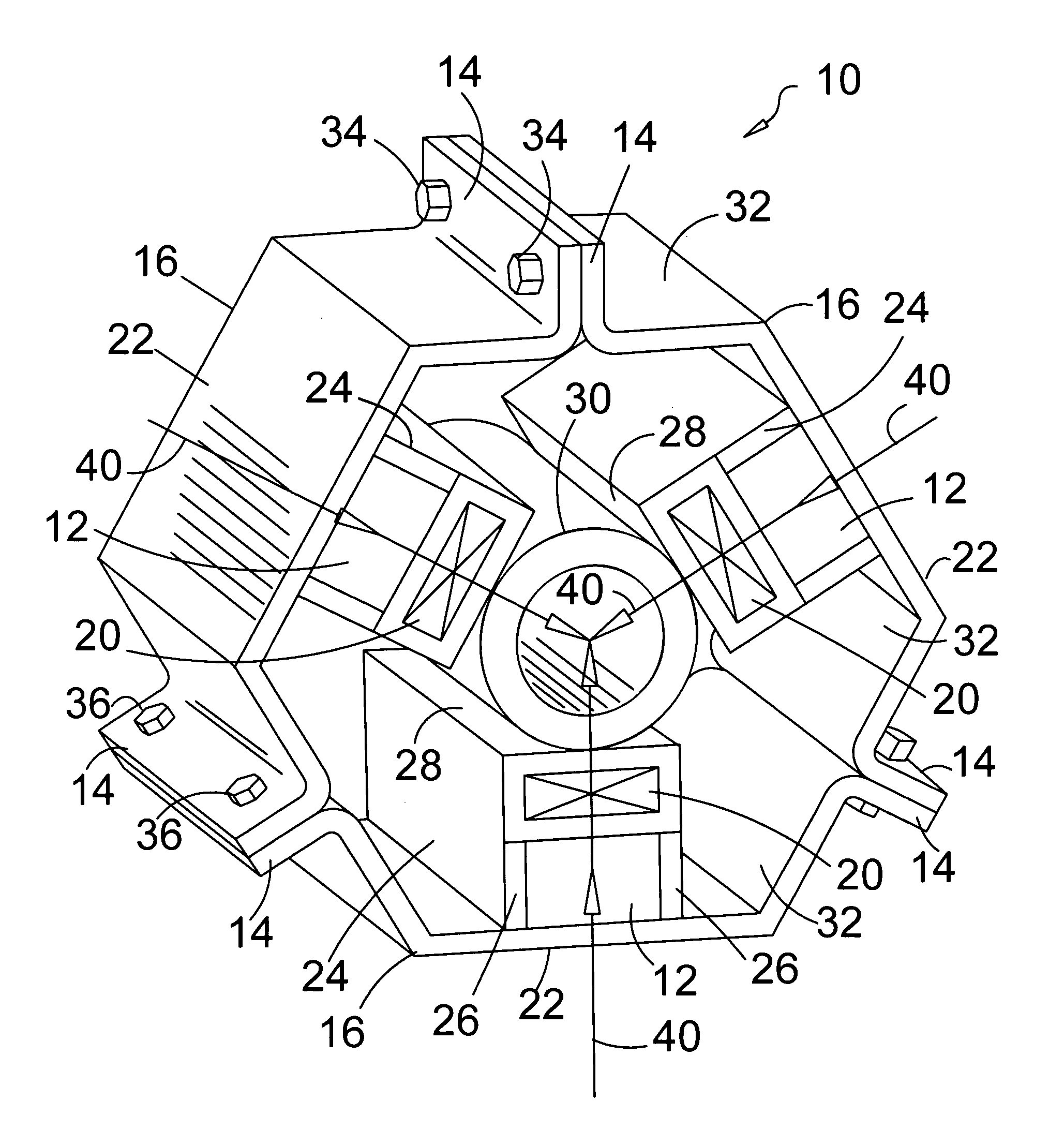
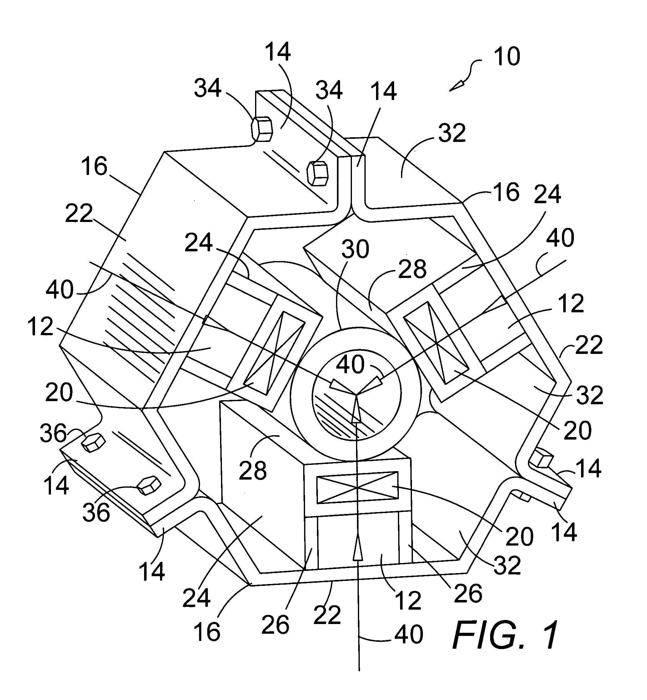
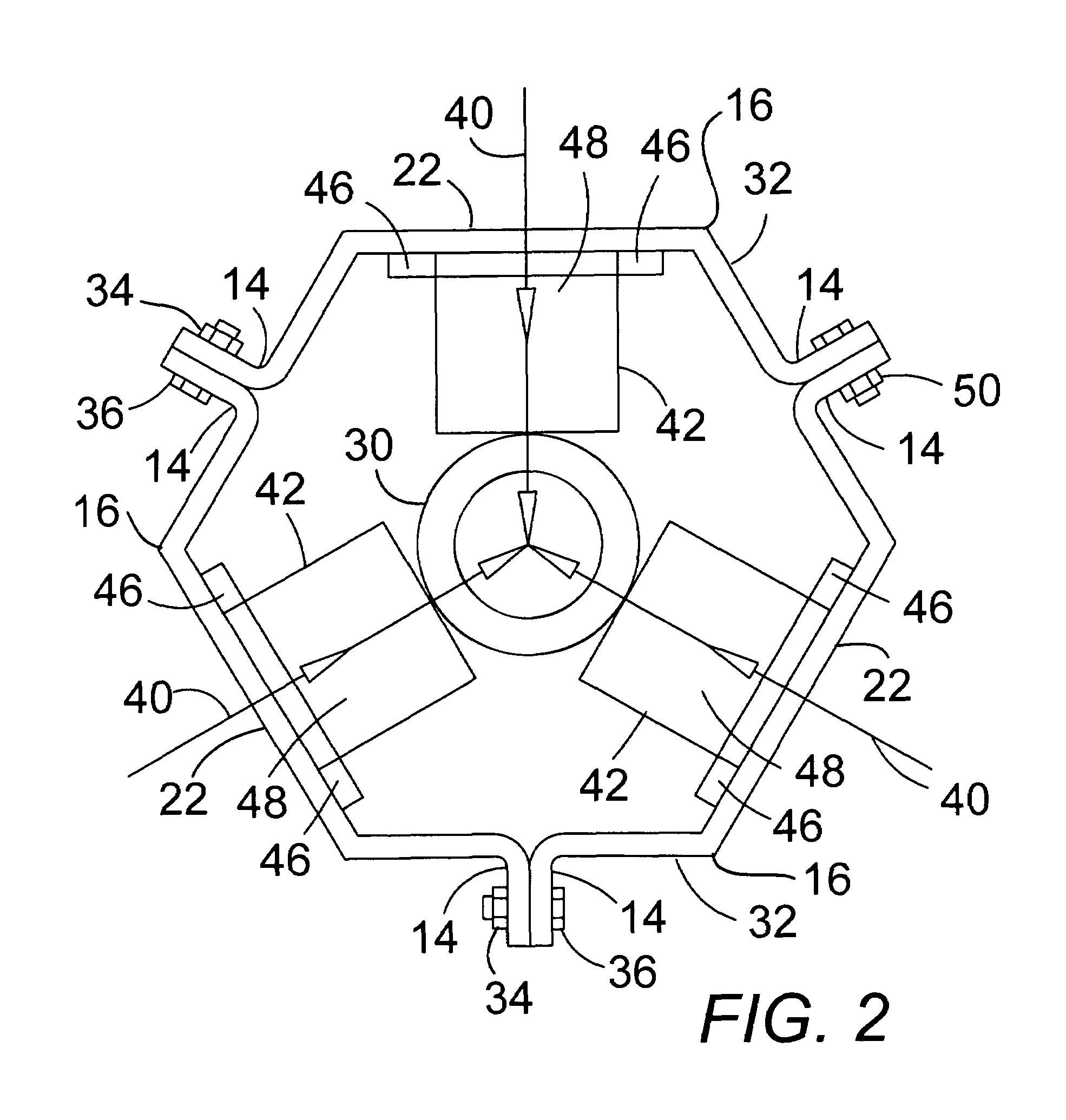
"The present invention provides a combination of three ferrite ceramic magnets housed in a stainless steel outer housing with a clamping mechanism that can be easily installed on a fuel line or other fluid conduit. The magnets are positioned close to the fuel line and are non-ferrous in their clamping mechanism to minimize magnetic interference with sensitive parts. The three magnets are evenly spaced and aligned in the same magnetic polar direction to optimize the magnetic effect on the fuel line. The clamping mechanism can be adjusted to fit different sizes of fuel lines. The magnetic material and size are important factors in making the product work. The invention is superior to existing methods of applying magnetic fields to fluids because it uses a better magnet type and size, and the magnetic field affects the fluids by causing clustered molecules to separate and become evenly distributed, improving fuel combustion and reducing emissions. The invention is easy to install and minimizes the effect of the magnetic field external to the fuel line."

Problems solved by technology

Unfortunately, vehicles today generally have a substantial amount of electronic equipment, including computer chips.
Strong magnetic fields have a deleterious affect on such devices.

Method used


Image

  • Device for focusing a magnetic field to treat fluids in conduits
  • Device for focusing a magnetic field to treat fluids in conduits
  • Device for focusing a magnetic field to treat fluids in conduits

Examples


Embodiment Construction

[0028]The embodiments discussed herein are merely illustrative of specific manners in which to make and use the invention and are not to be interpreted as limiting the scope of the instant invention.

[0029]While the invention has been described with a certain degree of particularity, it is to be noted that many modifications may be made in the details of the invention's construction and the arrangement of its components without departing from the spirit and scope of this disclosure. It is understood that the invention is not limited to the embodiments set forth herein for purposes of exemplification.

[0030]In the present invention, the geometry of the magnets used is optimized to create a device that maximizes the benefits of magnetizing a liquid. Although it is especially suitable for magnetizing fuels, such as propane, natural gas, gasoline, diesel etc., it may also be used to magnetize other liquids. Motor oil and other lubricants exhibit superior performance when routinely magneti...


PUM

PropertyMeasurementUnit
magneticaaaaaaaaaa
magnetic fieldaaaaaaaaaa
magnetic effectaaaaaaaaaa

Abstract

Three magnet casings are adjustably and removably attached to one another such that the device may snuggly fit about fluid conduits of differing diameters. An outer casing wall of ferrous content stainless steel confines the magnetic field. An inner magnet holder frame attached to the outer casing wall holds a magnet to the conduit and is fabricated of non-ferrous stainless steel to allow maximum trans mission of the magnetic field to the fluid in the non-ferrous section of the conduit around which the casings are attached together.

Description

BACKGROUND OF THE INVENTION[0001]1. Field of the Invention[0002]The present invention relates to applying magnetic fields to treat fluids and in particular to a new and improved device for magnetically treating liquids and gases which may removably and adjustably be attached to a tube having a fluid, such as fuel, running through it to produce a unique magnetic field focused in such a way so as to improve the physical properties of the liquid, such as improving the fuel for better combustion with fewer emissions and better mileage in vehicular fuels.[0003]2. Description of the Prior Art[0004]It is well known in the art of magnetism that applying a strong magnetic field to a substance changes the direction of the magnetic moments of individual atoms within the substance. This allows scientists to use nuclear magnetic resonance to determine the geometric structures of a variety of organic compounds, including proteins. This technology has also been developed to create magnetic resonan...

Claims


Application Information

Patent Timeline
Patent Type & Authority Patents(United States)
IPC IPC(8): C02F1/48F02M33/00
CPCC02F1/481F02M27/045
Inventor SISEMORE, STANLEY L.
Owner TRINITY REFINING & SAFETY SYST LLC
Learn More