
Flexible integrated photovoltaic roofing membrane and related methods of manufacturing same

a photovoltaic roof and integrated technology, applied in the field of building materials, can solve the problems of inability to meet the needs of modern systems, inability to meet the needs of consumers, and difficulty in and costly maintenance,

Active Publication Date: 2010-03-16
ELK PREMIUM BUILDING PROD
View PDF17 Cites 98 Cited by
  • Summary
  • Abstract
  • Description
  • Claims
  • Application Information

AI Technical Summary

Benefits of technology

The solution simplifies installation, reduces leakage risks, and enhances aesthetics by allowing solar power integration without the need for multiple holes, providing a cost-effective and visually appealing solar-powered system that supplements or replaces traditional electricity.

Problems solved by technology

Whether it be the initial costs associated with such off-grid systems or the relatively difficult and costly maintenance required, off-grid systems have typically not been accepted by the consumer market.
However, the fragility and high cost of the crystal materials, as well as the clearly distinguishable appearance of the panels from ordinary roofing shingles, has resulted in essentially a rejection of such system by the market place.
Unfortunately, even such modern systems suffer from deficiencies, such as the need to form multiple holes through the roof deck and into the attic area for each shingle member in order to electrically connect all of the shingle members to create a functional system.
As the number of holes formed through the roof deck increases, so too do the chances of leakage through the roof during inclement weather.
Moreover, making the electrical connections from one shingle member to the next, and then to the circuit breaker box of the home, is typically quite tedious and exhausting.
Even so, panels located in the middle of a roofing section tend to be aesthetically unpleasing as they detract from the section's homogeneous and symmetrical appearance.

Method used


Image

  • Flexible integrated photovoltaic roofing membrane and related methods of manufacturing same
  • Flexible integrated photovoltaic roofing membrane and related methods of manufacturing same
  • Flexible integrated photovoltaic roofing membrane and related methods of manufacturing same

Examples


Embodiment Construction

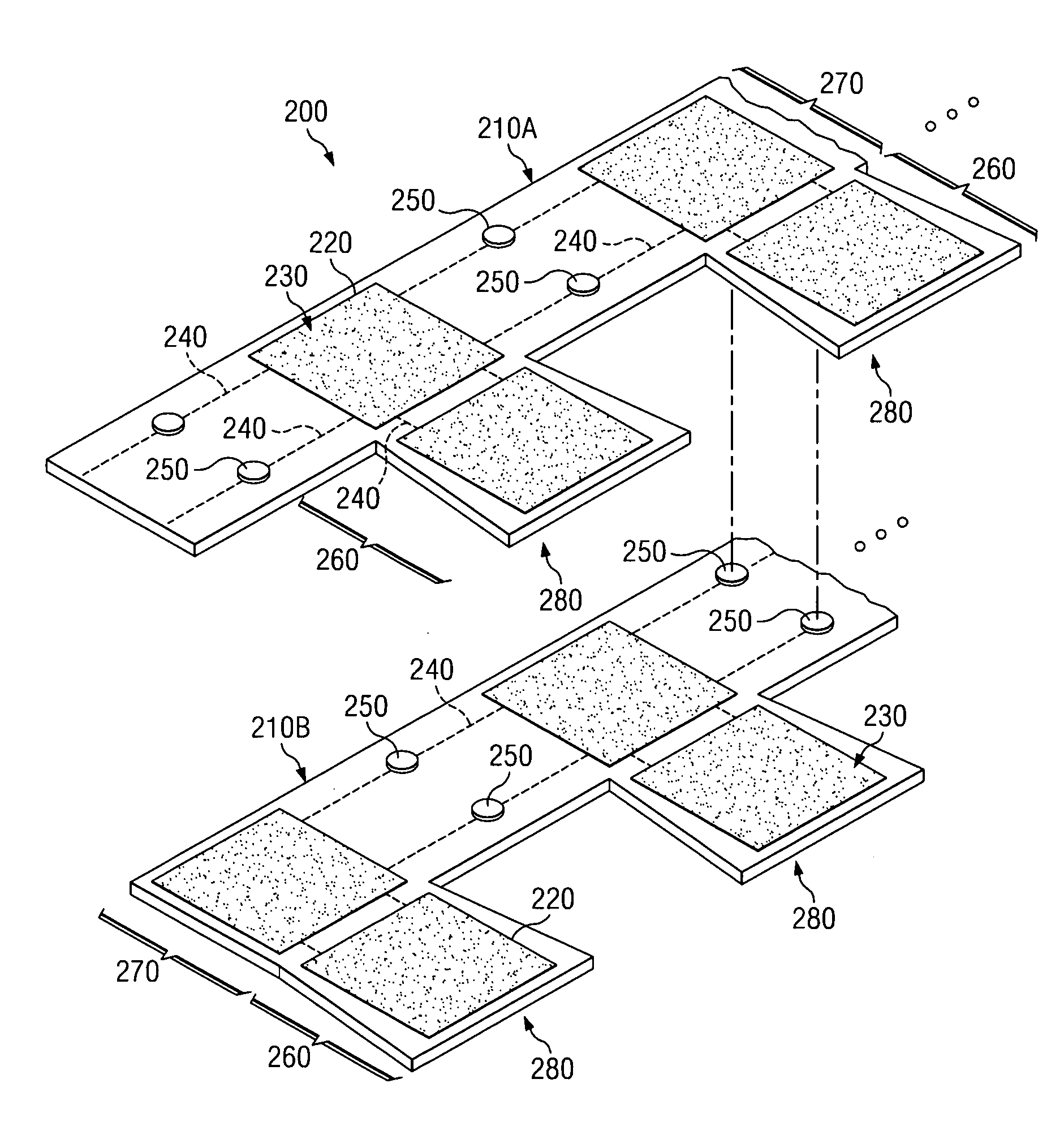
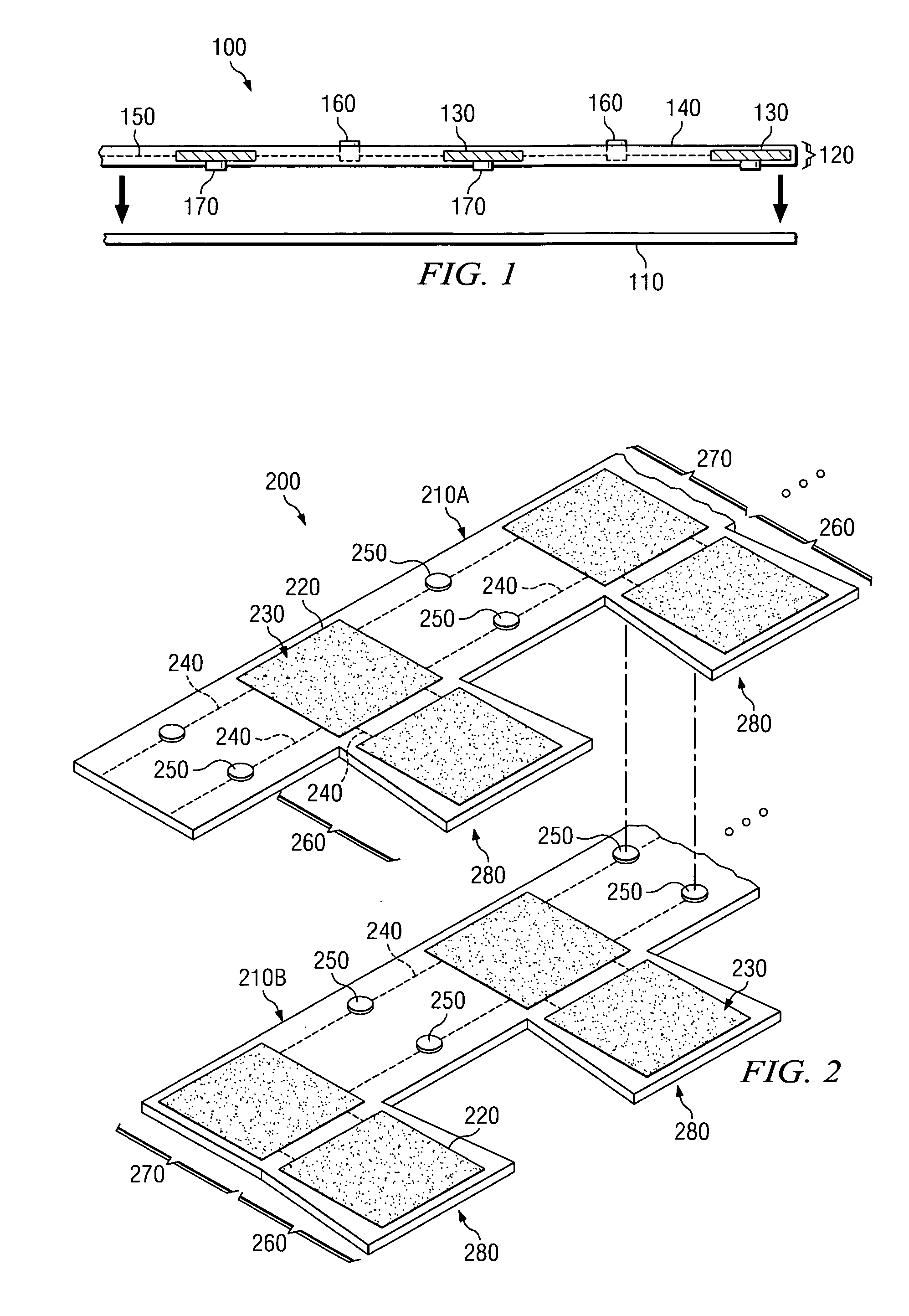
[0020]Referring initially to FIG. 1, illustrated is a side section view of one embodiment of an integrated photovoltaic roofing membrane 100 constructed according to the principles disclosed herein. As illustrated, the membrane 100 includes an underlayment layer 110 and a photovoltaic upper layer 120. In one embodiment, the underlayment 110 is a bituminous-based layer or fabric having the characteristics typically associated with roofing felts and other underlying layers of conventional roofing materials. In one example, the underlayment 110 may include Styrene-Butadiene-Styrene (SBS) or Atactic Polypropylene (APP), however it should be understood that the underlayment 110 is not limited to any particular composition.

[0021]The upper layer 120 of the membrane 100 is comprised of several parts. Initially, the upper layer 120 includes several photovoltaic solar elements 130 dispersed horizontally across the layer 120. The solar elements 130 function as solar panels to collect solar rad...


PUM

PropertyMeasurementUnit
lengthaaaaaaaaaa
flexibleaaaaaaaaaa
lengthaaaaaaaaaa

Abstract

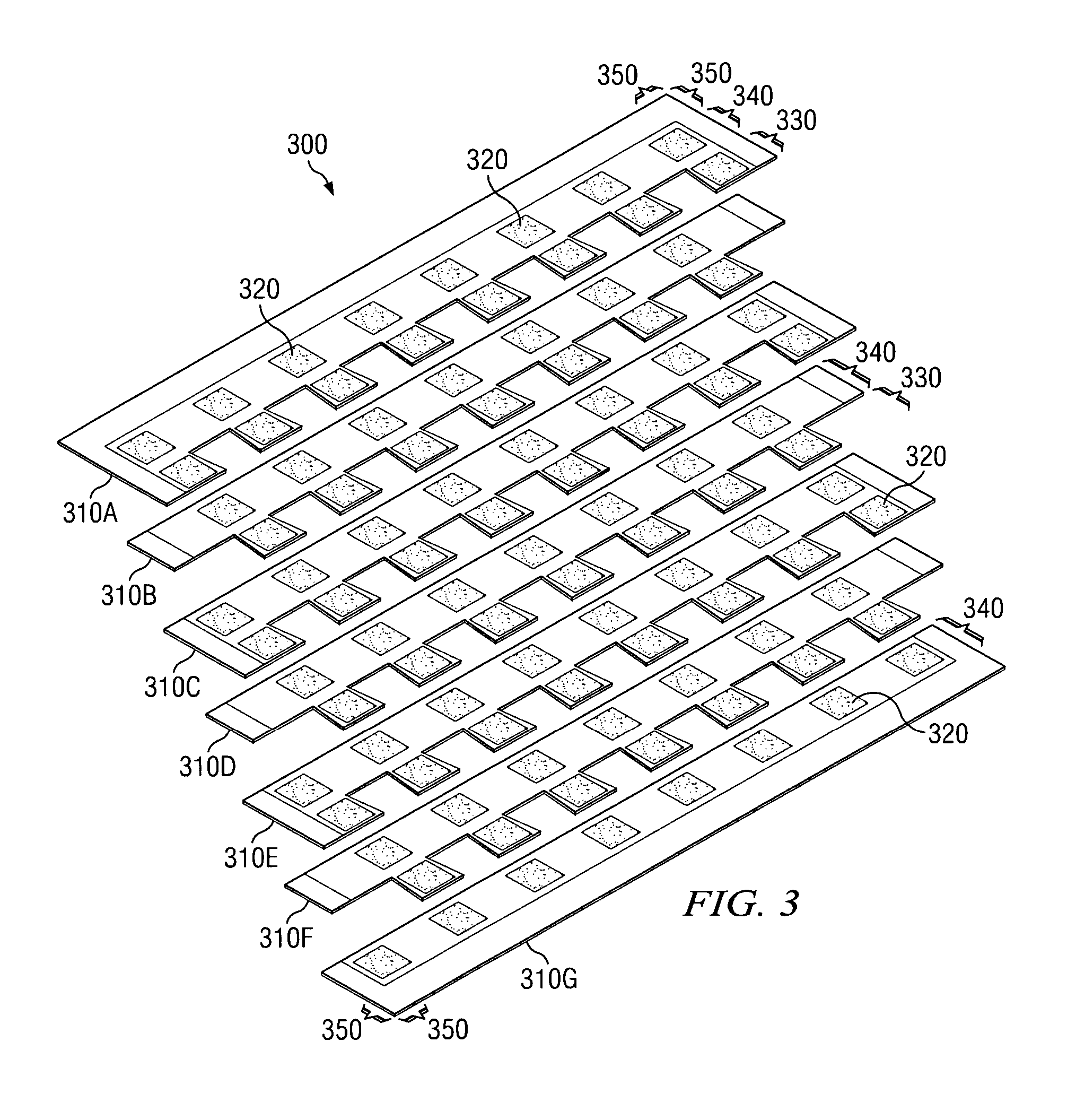
Disclosed herein are flexible, solar powered photovoltaic (PV) integrated roofing membrane and related methods of manufacturing such a membrane. The disclosed membrane and methods beneficially provide solar power to structures in either off-grid or on-grid connections. The roofing membrane may comprise multiple membrane strips or members having electrically interconnected photovoltaic solar elements. The membrane members preferably have distinct patterns for the solar elements located thereon that provide for coverage of entire sections, upon installation, as well as accommodate interconnections between the solar elements. Moreover, the membrane will appreciate the numerous types of patterns to achieve such purposed of full coverage and electrical coupling.

Description

CROSS-REFERENCE TO RELATED APPLICATION[0001]This Application claims the benefit of U.S. Provisional Application Ser. No. 60 / 545,016, filed on Feb. 17, 2004, and entitled “Integrated Photovoltaic Roofing Membrane and Related Methods of Manufacturing Same,” which is commonly assigned with the present application and incorporated herein by reference for all purposes. In addition, this Application is also related to co-pending U.S. patent application Ser. No. 11 / 051,839 entitled “Rigid Integrated Photovoltaic Roofing Membrane and Related Methods of Manufacturing Same,” filed on Feb. 4, 2005, which is commonly assigned with the present Application.TECHNICAL FIELD[0002]Disclosed embodiments herein relate generally to building materials for covering, for example, the roof deck of a building, and more particularly to a flexible integrated photovoltaic roofing membrane for use on the roof deck. Such membrane may comprise overlapping membrane members each having integrated and electrically in...

Claims


Application Information

Patent Timeline
Patent Type & Authority Patents(United States)
IPC IPC(8): H02N6/00B60K16/00E04D3/00E04D3/18E04D3/34E04D5/00E04D5/10E04D5/12E04D13/18H01L25/00H01L31/042H01L31/048H01L31/05
CPCE04D1/26H02S20/23Y02B10/12E04D2001/308Y02E10/50Y02B10/10E04D1/29H02S20/25
Inventor MCCASKILL, JOHN R.MAYTUBBY, C. DANIEL
Owner ELK PREMIUM BUILDING PROD
Learn More