Voltage controlled oscillator

a voltage control and oscillator technology, applied in the direction of pulse generation by logic circuits, pulse automatic control, pulse technique, etc., can solve the problems of output stop, unstable clock signal output from pll circuit, and sensitive even to power nois

Inactive Publication Date: 2010-03-16
LAPIS SEMICON CO LTD
View PDF9 Cites 4 Cited by
  • Summary
  • Abstract
  • Description
  • Claims
  • Application Information

AI Technical Summary

Benefits of technology

[0012]According to the present invention, it is possible to allow an auxiliary current to flow without depending upon the control voltage and cause the voltage controlled oscillator to reliably oscillate in an in-design operating region even when the element or circuit for converting the control voltage to the control current is in a non-operating state.

Problems solved by technology

And the PLL circuit provided with such a voltage controlled oscillator was accompanied by the problem that when an input clock was interrupted due to some reasons, the PLL circuit attempted to lock onto a signal having a low frequency to thereby reduce the control voltage and eventually led to an output stop.
There was also a fear that when the control voltage was low upon power-on or the like, for example, the PLL circuit could not be locked, so that a clock signal outputted from the PLL circuit became unstable.
Since the auxiliary current is simply determined based on a voltage between the power supply and ground, a problem arises in that it is sensitive even to power noise and ground noise.

Method used


Image

  • Voltage controlled oscillator
  • Voltage controlled oscillator
  • Voltage controlled oscillator

Examples


Embodiment Construction

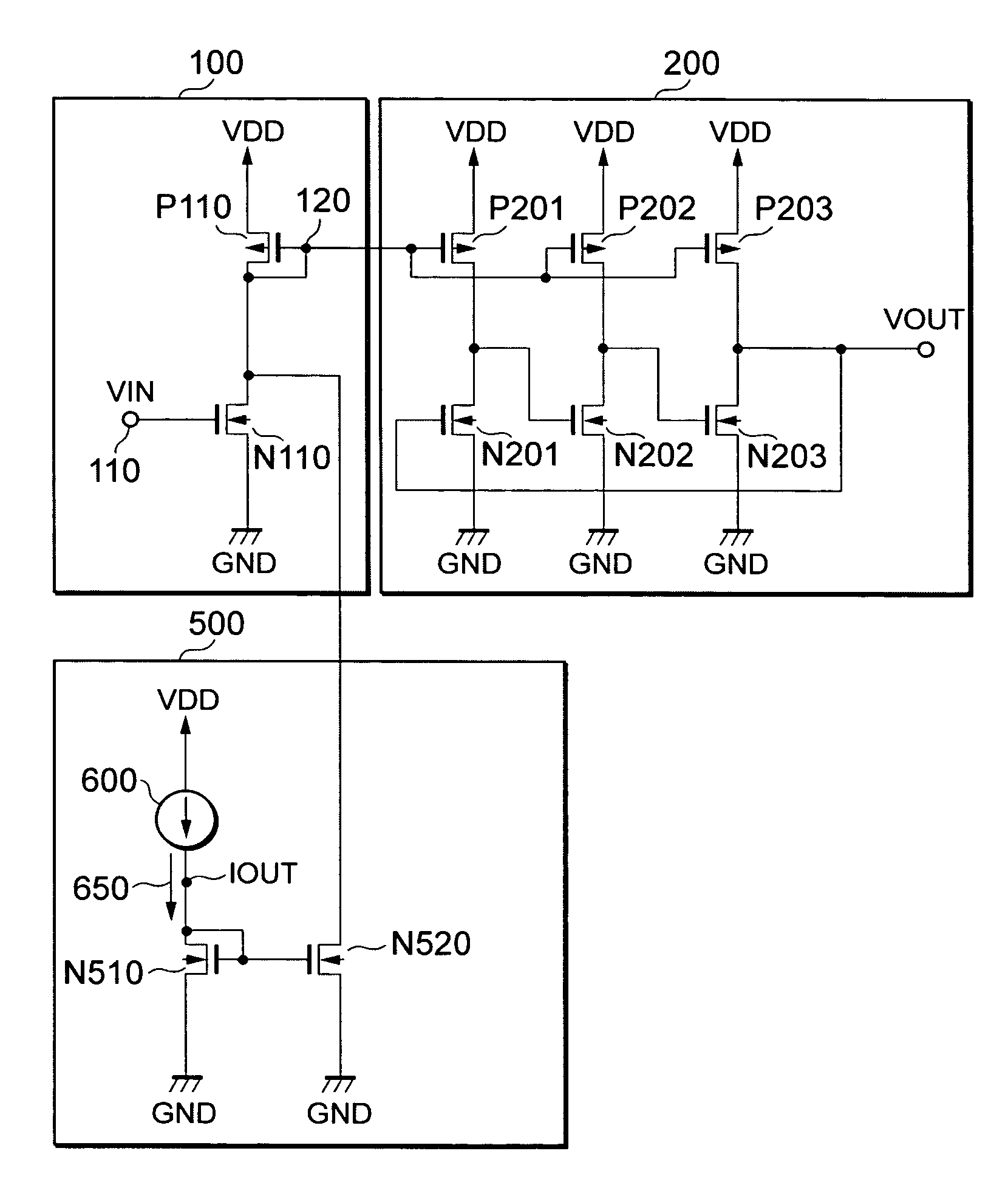
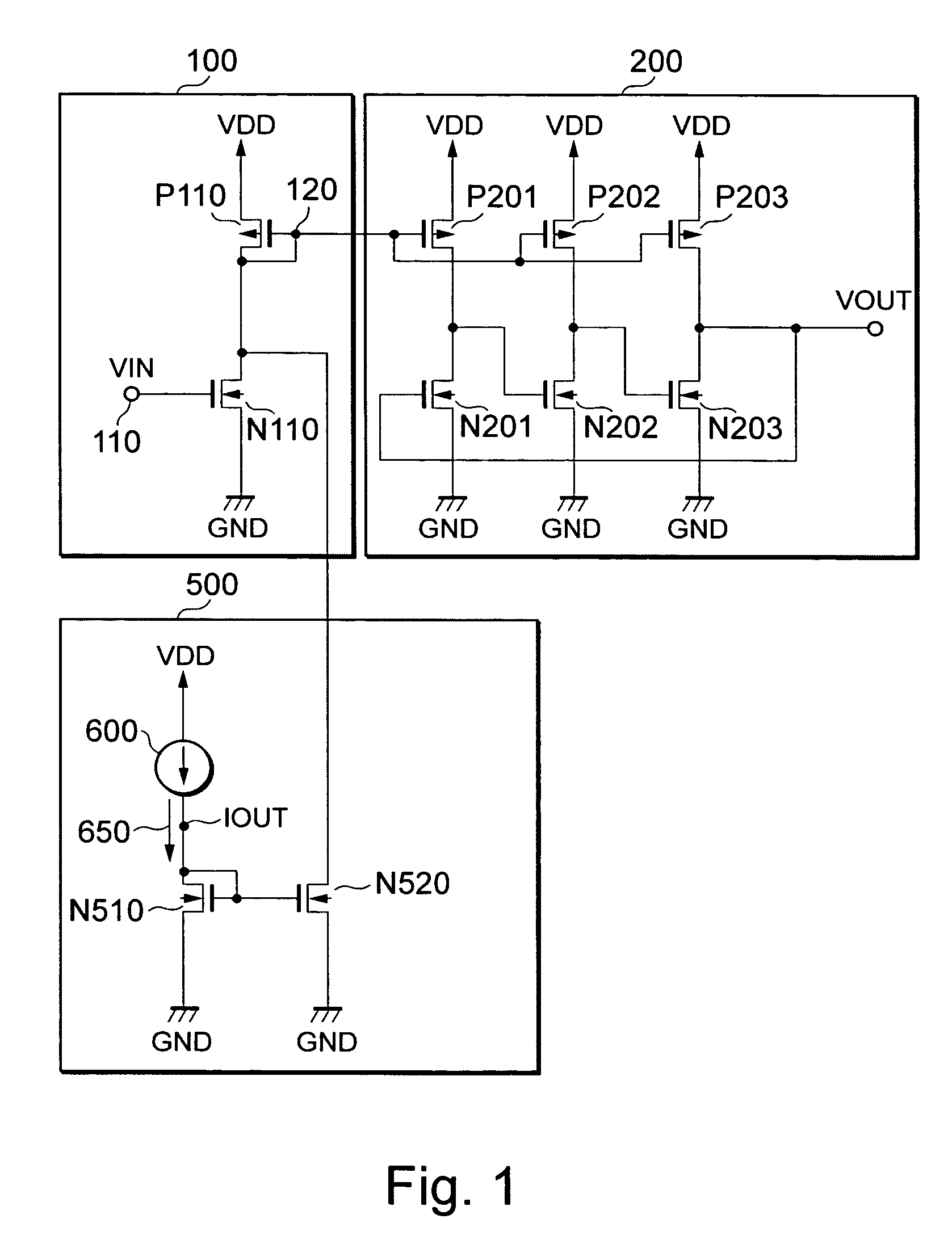
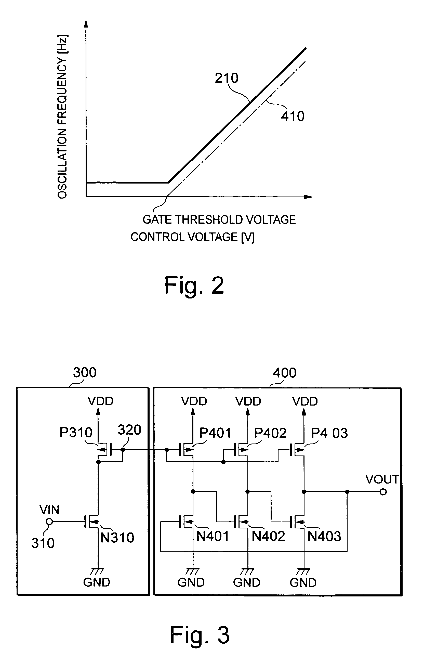
[0021]A preferred embodiment of a voltage controlled oscillator according to the present invention will next be described in detail with reference to the accompanying drawings. Prior to the description of the embodiment according to the present invention, a voltage controlled oscillator having the following voltage-current converter circuit will be explained as a comparative example. That is, the voltage-current converter circuit showing the comparative example has a semiconductor circuit to which a control voltage is inputted and which converts the control voltage to a control current corresponding to a voltage value thereof, but does not include a constant current adding circuit of the present invention, which adds a constant current to the control current. This voltage controlled oscillator will be explained with reference to FIGS. 3 and 4.

[0022]FIG. 3 shows a configuration of the voltage controlled oscillator according to the comparative example. The voltage controlled oscillato...


PUM


Abstract

A voltage controlled oscillator which performs an oscillating operation at a frequency corresponding to a control voltage, includes a voltage-current converter circuit which converts the control voltage to a control current corresponding to a voltage value thereof, and a ring oscillator through which an operating current corresponding to the control current generated by the voltage-current converter circuit is caused to flow, and which oscillates at a frequency corresponding to a current value thereof. The voltage-current converter circuit has a voltage-voltage converting circuit which inputs the control voltage therein and converts the same to a control current corresponding to the voltage value thereof, and an offset current generating circuit which adds a constant current to the control current.

Description

BACKGROUND OF THE INVENTION[0001]The present invention relates to a voltage controlled oscillator (VCO), and a startup circuit suitable for the voltage controlled oscillator.[0002]A voltage controlled oscillator is used in a PLL (Phase-Locked Loop) circuit or the like. As the voltage controlled oscillator of the PLL circuit, may be mentioned, for example, a ring oscillator comprised of inverters, a differential ring oscillator, etc. Any of such voltage controlled oscillators changes an amount of current supplied to each of inverter circuits or differential circuits used as components of the ring oscillator in accordance with a control voltage to change a delay time of each inverter, thereby changing an oscillation frequency. Thus, the voltage controlled oscillator is provided with a voltage-current converter circuit for converting a control voltage to a control current in addition to an oscillator.[0003]In the voltage-current converter circuit of the conventional voltage controlled ...

Claims


Application Information

Patent Timeline
Patent Type & Authority Patents(United States)
IPC IPC(8): H03K3/03
CPCH03L7/0995
Inventor HIRATA, MANABUFUEKI, YOICHITAJIMA, KAZUYUKI
Owner LAPIS SEMICON CO LTD
Why Eureka
Try Eureka