Gas sensor

a gas sensor and sensor output technology, applied in the field of gas sensors, can solve the problems of difficult stable measurement, lower measurement accuracy, and drawbacks of the lamininate-type gas sensor, and achieve the effects of suppressing oscillation, suppressing oscillation, and suppressing oscillation

Active Publication Date: 2014-07-08
NGK SPARK PLUG CO LTD
View PDF6 Cites 3 Cited by
  • Summary
  • Abstract
  • Description
  • Claims
  • Application Information

AI Technical Summary

Benefits of technology

[0014]According to the above gas sensor (1) of the invention, since the two cells electrically communicate with each other through the leakage portion, a delay (phase delay) in change in the output voltage of the oxygen-concentration detection cell in relation to a change in the current of the oxygen pump cell is reduced. Accordingly, it is possible to suppress the occurrence of oscillation in feedback control performed by a control circuit which controls the current of the oxygen pump cell in accordance with a change in the output voltage of the oxygen-concentration detection cell. That is, when the pump current of the oxygen pump cell is changed, the above configuration prevents the output voltage of the oxygen-concentration detection cell from being greatly influenced, whereby fluctuation of the sensor output is suppressed. Notably, as used herein, the expression “electrically communicate” means that a path exists through which electrons and / or ions move.
[0015]Further, since the leakage portion is provided in the gas sensor, it is possible to suppress oscillation without preparing a dedicated control circuit which includes a constituent element for suppressing oscillation stemming from feedback control, such as a high pass filter including a resistor and a capacitor. Accordingly, it is possible to insure compatibility of the control circuit with a gas sensor which does not cause the control circuit to oscillate and which does not require a dedicated control circuit. In addition, since constituent elements, such as a resistor and a capacitor, for suppressing oscillation are not additionally provided in the control circuit, the manufacturing cost can be reduced.
[0016]Incidentally, in the above-described gas sensor (1) of the invention, the insulating layer, which insulates the oxygen-concentration detection cell and the oxygen pump cell from each other, is interposed between the oxygen-concentration detection cell and the oxygen pump cell. Further, the leakage portion, which electrically connects the oxygen-concentration detection cell and the oxygen pump cell, is provided separately from the insulating layer. Oscillation in feedback control can be suppressed by establishing electrical communication between the two cells. Therefore, the gas sensor may be configured such that electrical communication is established between the oxygen-concentration detection cell and the oxygen pump cell by interposing an electrical connection layer between the two cells without providing the insulating layer therebetween. However, if such a connection layer is provided, a large voltage (also referred to as “leakage voltage”) is produced due to a current (also referred to as “leakage current”) flowing between the two cells via the connection layer and is superimposed on the output voltage of the oxygen-concentration detection cell. As a result, the measurement accuracy of the gas sensor may decrease. In contrast, the gas sensor (1) of the invention is configured such that the insulating layer is interposed between the oxygen-concentration detection cell and the oxygen pump cell and the leakage portion is separately provided at a portion of the insulating layer. Therefore, superposition of a leakage voltage on the output voltage of the oxygen-concentration detection cell can be adequately suppressed. Accordingly, it is possible to suppress oscillation in feedback control, while preventing a decrease in measurement accuracy of the gas sensor due to the leakage current.
[0019]According to the gas sensor (2), the leakage portion is disposed such that it overlaps a region where heating is performed by the heating element. Therefore, the temperature of the leakage portion is properly controlled, whereby the electrical conductivity of the zirconia which constitutes the leakage portion can be properly maintained. Accordingly, it is possible to more reliably suppress oscillation of feedback control and to prevent fluctuation of the sensor output.
[0022]According to the above gas sensor (3), the occupation ratio of the leakage portion in relation to the insulating layer can be properly adjusted by making the area of the leakage portion smaller than 50% the sum of the area of the insulating layer and the area of the leakage portion (i.e., by making the area of the leakage portion smaller than the area of the insulating layer). Accordingly, oscillation in the feedback control is suppressed in a satisfactory manner by the leakage current, and the leakage voltage superimposed on the output voltage of the oxygen-concentration detection cell is adequately suppressed, whereby a reduction in measurement accuracy of the gas sensor is prevented due to the leakage voltage. Notably, it is sufficient for the leakage portion to have an area within the above-described range on only one of arbitrary cross sections of the insulating layer taken perpendicular to the lamination direction. Preferably, the leakage portion has an area within the above-described range on more than one of possible cross sections. More preferably, the leakage portion has an area within the above-described range on all the cross sections.
[0024]According to the gas sensor (4), the outer surface of the leakage portion can be prevented from exposure to exhaust gas. Thus, adhesion of carbon (soot) or a water droplet on the outer surface of the leakage portion can be suppressed. Accordingly, it is possible to prevent the occurrence of blackening of the gas sensor due to adhesion of carbon to the leakage portion and the generation of cracks in the gas sensor due to adhesion of water droplets to the leakage portion. The occurrence of blackening and the generation of cracks would otherwise result in a sensor failure.

Problems solved by technology

However, such a laminate-type gas sensor has a drawback.
When the time lag becomes excessively large, the control circuit oscillates and the sensor output fluctuates, which makes stable measurement difficult and lowers measurement accuracy.
However, the use of such a dedicated control circuit may impair compatibility of the control circuit with a gas sensor of a type which does not cause the control circuit to oscillate and which avoids the necessity of providing a high pass filter in the control circuit.
Also, since a resistor and a capacitor must be added in order to provide a high pass filter in the control circuit, the manufacturing cost may thereby increase.

Method used


Image

  • Gas sensor
  • Gas sensor
  • Gas sensor

Examples


modification 1

[0188]C1.

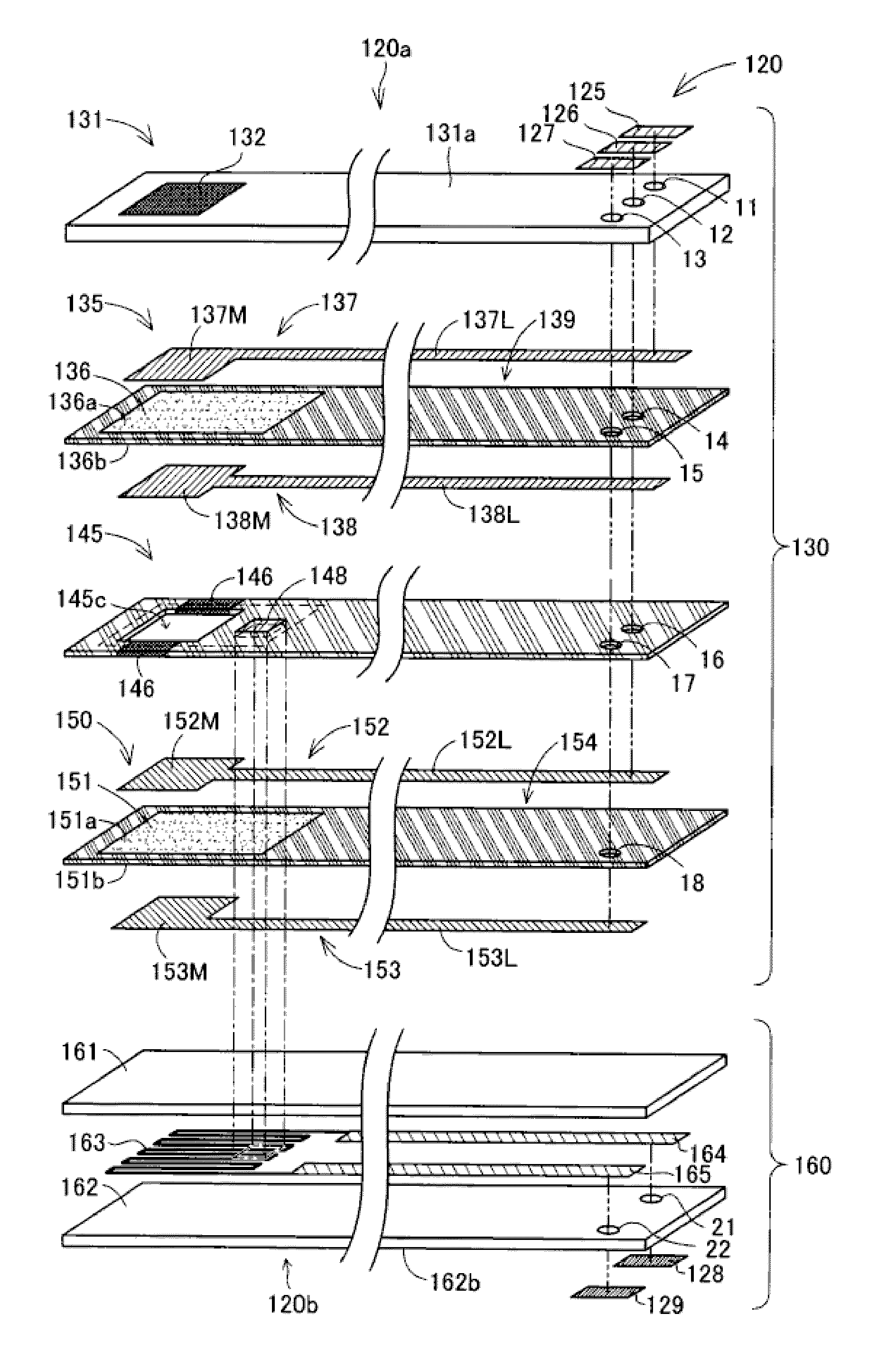
[0189]In the gas sensor 100 of the above-described embodiment, the leakage portion 148 is formed in a region which overlaps the heating resistor 163 of the heater element 160 when the gas sensor element 120 is viewed in the lamination direction. The leakage portion 148 may also be provided outside that region. However, forming the leakage portion 148 in such a region is preferred, because the temperature of the leakage portion 148 can be adequately controlled. Notably, the leakage portion 148 may be provided in a region near the heating resistor 163 which can be heated by the heating resistor 163.

modification 2

[0190]C2.

[0191]In the above-described embodiment, the control circuit 200 is configured by combining the PID element 210 and the operational amplifier 211. However, the control circuit 200 may have a different configuration.

[0192]C3. Modification 3:

[0193]In the above-described embodiment, each of the oxygen pump cell 135 and the oxygen-concentration detection cell 150 is configured such that the paired electrodes 137, 138 or the paired electrodes 152, 153 are disposed on opposite surfaces of the first solid electrolyte member 136 or the second solid electrolyte member 151. However, each of the oxygen pump cell 135 and the oxygen-concentration detection cell 150 may be configured such that the paired electrodes 137, 138 or the paired electrodes 152, 153 are disposed on one surface of the first solid electrolyte member 136 or the second solid electrolyte member 151. In the above-described embodiment, the paired electrodes 137, 138 of the oxygen pump cell 135 and the paired electrodes ...


PUM

PropertyMeasurementUnit
output voltageaaaaaaaaaa
concentrationaaaaaaaaaa
meandering shapeaaaaaaaaaa

Abstract

A gas sensor (100) includes an oxygen pump cell (135) and an oxygen-concentration detection cell (150) laminated together with a spacer (145) interposed therebetween. The spacer (145) has a gas detection chamber (145c) which faces electrodes (137, 152) of the cells (135, 150). The oxygen-concentration detection cell (150) produces an output voltage corresponding to the concentration of oxygen in the gas detection chamber (145c). The oxygen pump cell (135) pumps oxygen into and out of the measurement chamber (145c) such that the output voltage of the oxygen-concentration detection cell (150) becomes equal to a predetermined target voltage. A leakage portion mainly formed of zirconia is disposed between which electrically connects the oxygen-concentration detection cell (150) and the oxygen pump cell (135).

Description

BACKGROUND OF THE INVENTION[0001]1. Field of the Invention[0002]The present invention relates to a gas sensor.[0003]2. Description of Related Art[0004]An example of known gas sensors for detecting a specific gas is an oxygen sensor which includes a cell having a pair of electrodes disposed on the outer surface of a solid electrolyte member and which measures the air-fuel ratio of air-fuel mixture supplied to an internal combustion engine (hereinafter referred to as the air-fuel ratio of the internal combustion engine). Particularly, a laminate-type gas sensor is known in which two cells are stacked or laminated with a measurement chamber formed therebetween, and which is adapted to detect the concentration of oxygen contained in exhaust gas over the full range of the air-fuel ratio of the internal combustion engine (see Patent Document 1 below, etc.). In the laminate-type gas sensor, a first cell (also called an “oxygen-concentration detection cell”) outputs to an external control c...

Claims


Application Information

Patent Timeline
Patent Type & Authority Patents(United States)
IPC IPC(8): G01N27/419G01N27/406G01N27/407G01N27/409
CPCG01N27/406G01N27/4062G01N27/407G01N27/409G01N27/41G01N27/419
Inventor ITO, TETSUYATERAMOTO, SATOSHIMORI, KENTARO
Owner NGK SPARK PLUG CO LTD
Why Eureka
Try Eureka