Electromagnetic-shielding device

a shielding device and electromagnetic technology, applied in the direction of electrical apparatus casings/cabinets/drawers, rack/frame construction, support structure mounting, etc., can solve the problems of increasing the cost of materials, reducing the accuracy of assembly, and increasing the difficulty of welding and applying materials

Inactive Publication Date: 2010-03-16
HORNG CHIN FU
View PDF17 Cites 10 Cited by
  • Summary
  • Abstract
  • Description
  • Claims
  • Application Information

AI Technical Summary

Benefits of technology

[0010]The primary objective of the present invention is to provide an electromagnetic-shielding device, which employs a housing or a central plate and at least one positioning and leaning wall in order to let an electromagnetic-shielding mask be easily and precisely covered an electric component in an electronic device. So that the assembling accuracy is promoted and the error possibility is decreased.
[0011]The secondary objective of the present invention is to provide an electromagnetic-shielding device, which structure can be made easily so as to save the cost, including material and labor.
[0015]The electromagnetic-shielding device of the present invention can avoid that the electric component in the electronic device is interfered by electromagnetic wave. The positioning and leaning wall functions to help that the electromagnetic-shielding mask is accurately mounted on the housing or the central plate in order to promote the precision of assembling the electronic device and decrease the possibility of generating errors. The electromagnetic-shielding device can be constructed very easily due to its simple structure. Further more, mounting the electromagnetic-shielding device lets a conductive sponge be no more existed. Therefore, the material cost for avoiding electromagnetic interference can be highly decreased.

Problems solved by technology

However, if the way of welding, such as SMT, is adopted, the materials for welding and applying are then limited.
Further, the procedures are complicate and the cost of materials is relatively higher.
On the other hand, the electromagnetic-shielding mask is not easily dismantled while in maintenance.
Therefore, how to provide an advanced structure for the electromagnetic-shielding mask and the housing to be simply and effectively installed on is an important issue to the skilled people.

Method used


Image

  • Electromagnetic-shielding device
  • Electromagnetic-shielding device
  • Electromagnetic-shielding device

Examples


Embodiment Construction

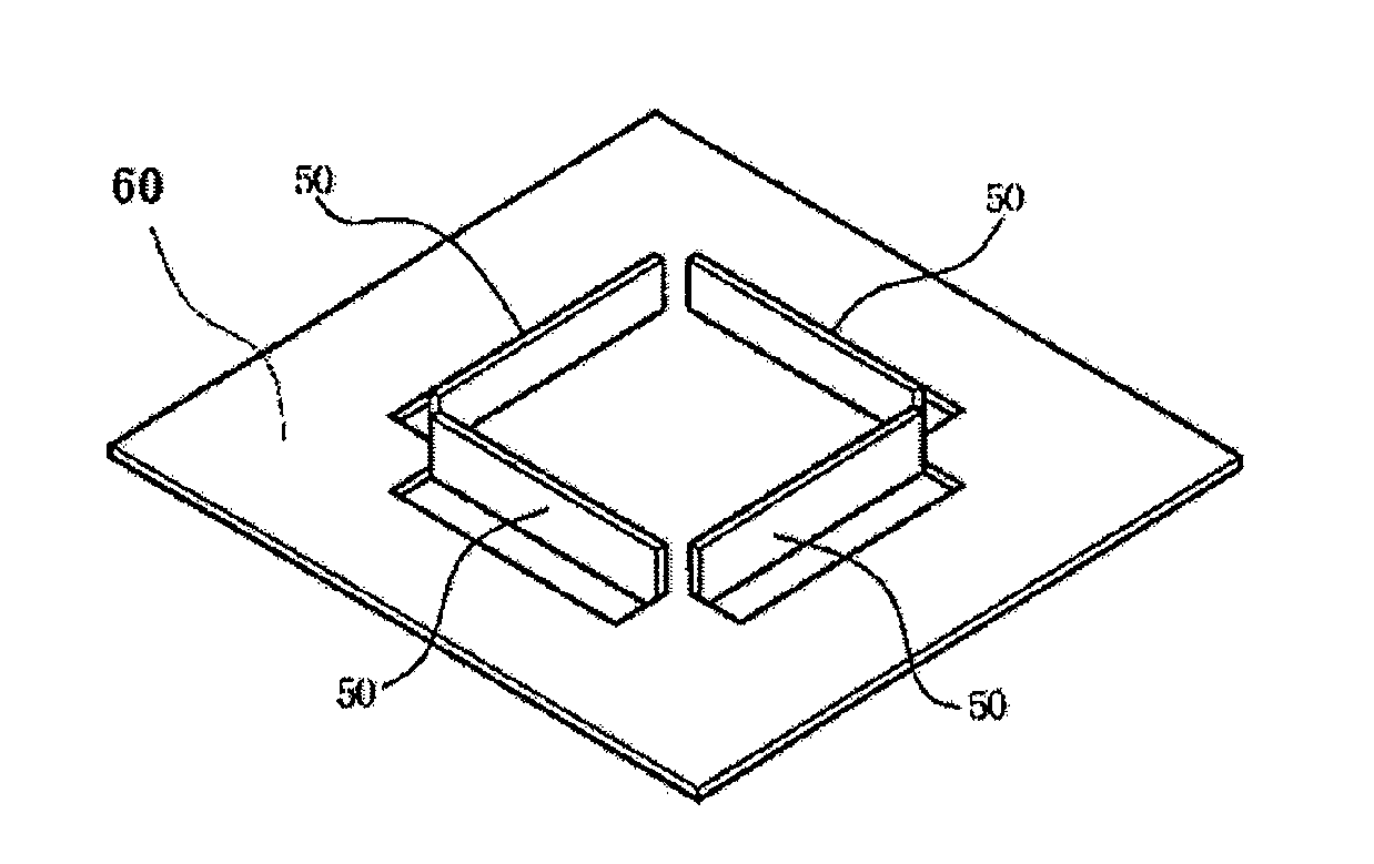
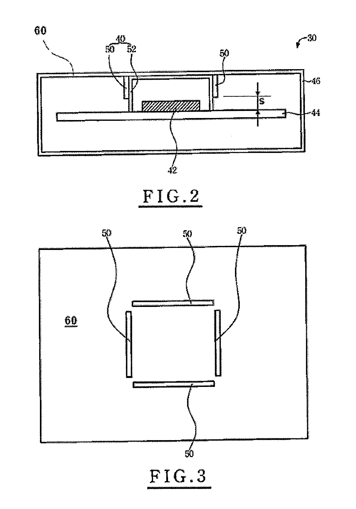
[0025]With reference to FIG. 2, which illustrates a schematic side sectional view of an electromagnetic-shielding device 40 of the present invention. The electromagnetic-shielding device 40 is disposed in an electronic device 30 to avoid that an electric component 42 in the electronic device 30 is interfered by electromagnetic wave, in which the electric component 42 is normally disposed in a PCB 44. A laminate member 60 is defined inside the electronic device 30. As shown in FIG. 2, the laminate member 60 is a part of a housing 46 of the electronic device 30.

[0026]The electromagnetic-shielding device 40 including a positioning and leaning wall 50 and an electromagnetic-shielding mask 52. In practice, the positioning and leaning wall 50 may be more than one. There are two positioning and leaning walls 50 disposed at both sides respectively in FIG. 2. Each positioning and leaning wall 50 is fixed on the laminate member 60 and elongated toward the electric component 42. Each side surf...


PUM


Abstract

An electromagnetic-shielding device disposed in an electronic device prevents that an electric component in the electronic device is interfered by electromagnetic wave. The electromagnetic-shielding device has at least one positioning and leaning wall, which is mounted on a laminate member as a part of a housing of the electronic device or a central plate within the electronic device. By means of the positioning and leaning wall, an electromagnetic-shielding mask is conveniently mounted within the electronic device so as to cover the electronic component.

Description

BACKGROUND OF THE INVENTION[0001]1. Field of the Invention[0002]The present invention generally relates to an electromagnetic-shielding device, more particular to an electromagnetic-shielding device, which employs a laminate member and four positioning and leaning walls in order to let an electromagnetic-shielding mask be easily and precisely covered an electric component in an electronic device.[0003]2. Description of the Prior Art[0004]For avoiding the electric components as CPUs, chips, etc. of the PCBs in a mobile phone, PDA, laptop, etc. being not interfered by outside EMI (electromagnetic interference), the components just can work properly. On the other hand, the EMI leaking from some powered electric components should also be shielded to not bother other outside electronic devices and organisms.[0005]An electromagnetic-shielding mask in prior arts is mounted on PCB and covers electric components. Such electromagnetic mask is mounted on PCB by the ways of welding, fastening, ...

Claims


Application Information

Patent Timeline
Patent Type & Authority Patents(United States)
IPC IPC(8): H05K9/00
CPCH05K9/0037H05K9/0049
Inventor HORNG, CHIN-FU
Owner HORNG CHIN FU
Why Eureka
Try Eureka