Semiconductor integrated circuit, standard cell, standard cell library, semiconductor integrated circuit designing method, and semiconductor integrated circuit designing equipment
a technology of semiconductor integrated circuit and design method, which is applied in the direction of instruments, originals for photomechanical treatment, optics, etc., can solve the problems of increased propagation delay time, delay in tat (turn around time), and increased processing amoun
- Summary
- Abstract
- Description
- Claims
- Application Information
AI Technical Summary
Benefits of technology
Problems solved by technology
Method used
Image
Examples
embodiment 1
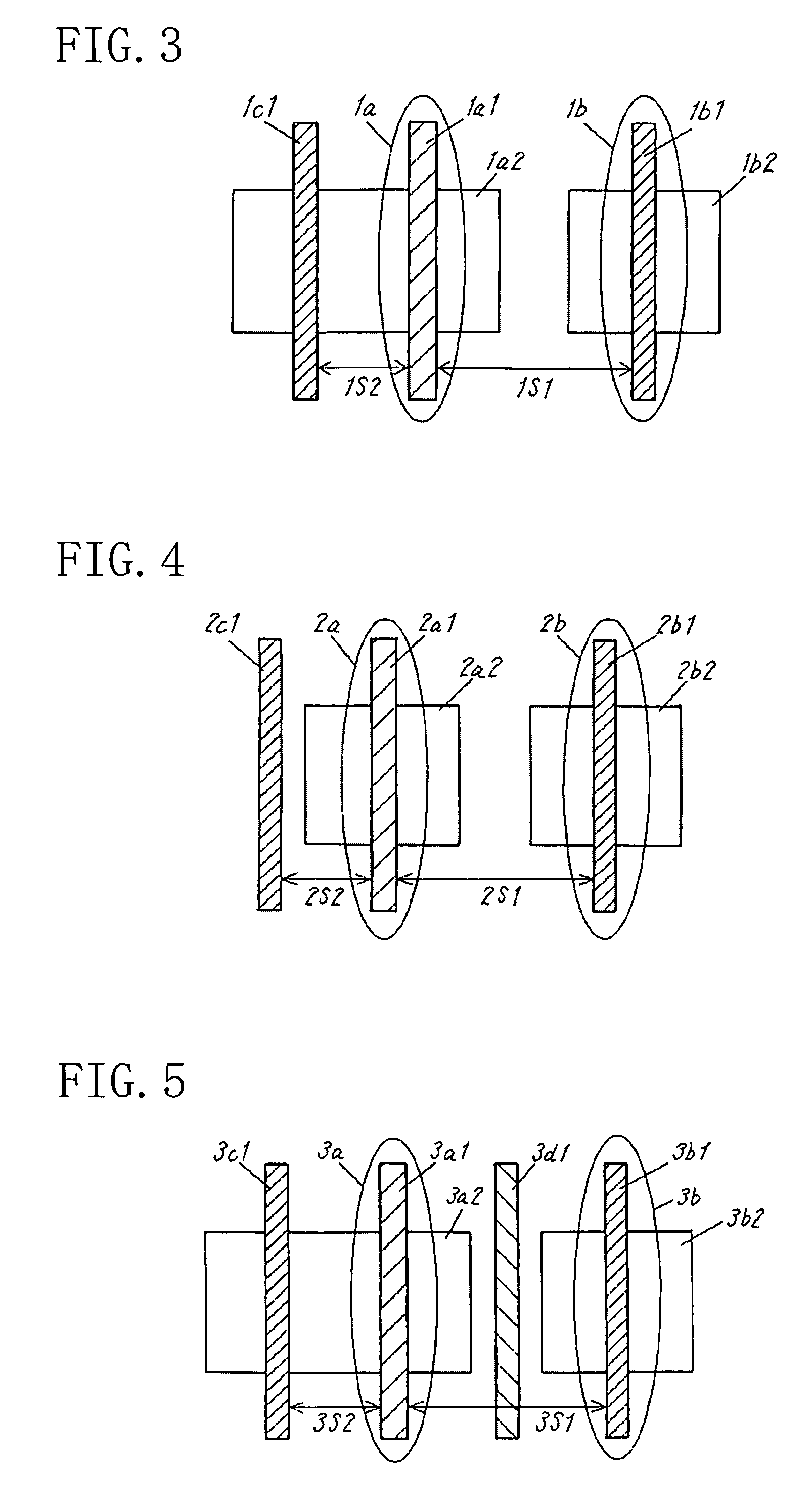
[0058]FIG. 3 is a layout diagram showing a layout pattern of a semiconductor integrated circuit according to Embodiment 1 of the present invention. In FIG. 3, a transistor 1b and a gate 1c1 are arranged on the respective sides of an active transistor 1a. The active transistor 1a is formed of a gate 1a1 and a diffusion region 1a2 while the transistor 1b is formed of a gate 1b1 and a diffusion region 1b2. The transistor 1b and the gate 1c1 are arranged adjacent to the active transistor 1a in a direction intersected at a right angle with a direction that the gate 1a1 extends.
[0059]The gate 1a1, the gate 1b1, and the gate 1c1 are arranged so that a space 1S1 between the gate 1a1 and the gate 1b1 is larger than a space 1S2 between the gate 1a1 and the gate 1c1 (for example, the space 1S1 is set so as to be two times, preferably, three times or more the space 1S2). The arrangement in which the space between the gate 1a1 and the gate 1b1 is set wide reduces the optical proximity effect tha...
embodiment 2
[0060]FIG. 4 is a layout diagram showing a layout pattern of a semiconductor integrated circuit according to Embodiment 2 of the present invention. In FIG. 4, an active transistor 2a is formed of a gate 2a1 and a diffusion region 2a2 while a transistor 2b is formed of a gate 2b1 and a diffusion region 2b2.
[0061]Difference of FIG. 4 from FIG. 3 lies in that a dummy gate 2c1 is provided in lieu to the gate 1c1. Even with the dummy gate 2c1, the arrangement in which the space between the gate 2a1 and the gate 2b1 is set wide attains the same effects as those in Embodiment 1.
embodiment 3
[0062]FIG. 5 is a layout diagram showing a layout pattern of a semiconductor integrated circuit according to Embodiment 3 of the present invention. In FIG. 5, an active transistor 3a is formed of a gate 3a1 and a diffusion region 3a2 while a transistor 3b is formed of a gate 3b1 and a diffusion region 3b2.
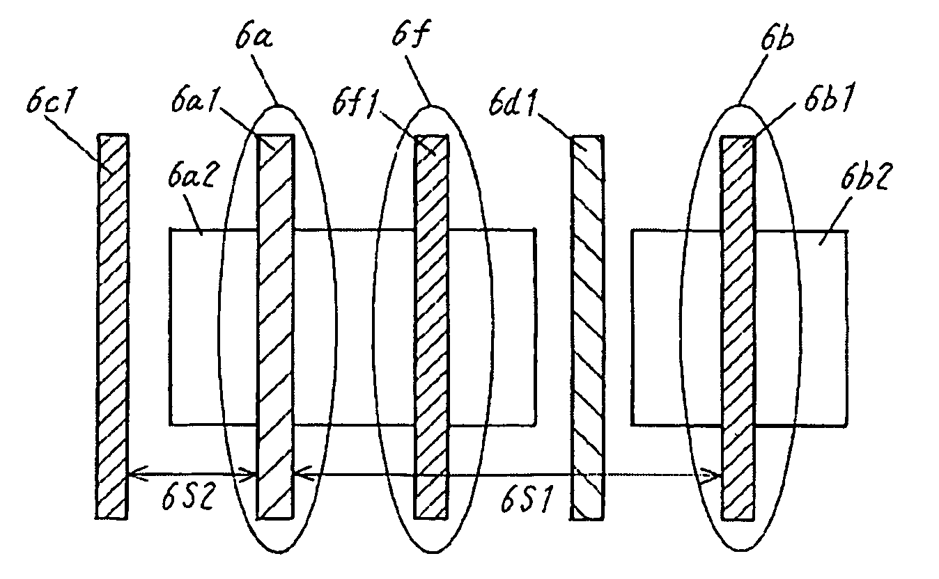
[0063]Difference of FIG. 5 from FIG. 3 lies in that a dummy gate 3d1 is arranged in parallel to the gate 3a1 between the gate 3a1 of the active transistor 3a and the gate 3b1 of the transistor 3b. When the additional gate 3d1 is interposed between the gate 3a1 of the active transistor 3a and the gate 3b1 of the transistor 3b, as shown in FIG. 5, influence of dimensional dispersion by the optical proximity that the gate 3b1 of the transistor 3b gives to the gate 3a1 of the active transistor 3a can be suppressed further than that in Embodiment 1.
PUM
| Property | Measurement | Unit |
|---|---|---|
| gate length | aaaaa | aaaaa |
| propagation delay time | aaaaa | aaaaa |
| temperature | aaaaa | aaaaa |
Abstract
Description
Claims
Application Information
 - R&D
- Intellectual Property
- Life Sciences
- Materials
- Tech Scout
- Unparalleled Data Quality
- Higher Quality Content
- 60% Fewer Hallucinations
Browse by: Latest US Patents, China's latest patents, Technical Efficacy Thesaurus, Application Domain, Technology Topic, Popular Technical Reports.
© 2025 PatSnap. All rights reserved.Legal|Privacy policy|Modern Slavery Act Transparency Statement|Sitemap|About US| Contact US: help@patsnap.com


