
Airfoil embodying mixed loading conventions

a technology of airfoils and loading conventions, applied in the field of airfoils, can solve the problems of airfoils being in an unfavorable operational regime, airfoils not fully understanding the underlying physics governing the generation of pressure losses, airfoils not fully understanding the underlying physics, etc., to achieve the effect of reducing the pressure losses experienced

Active Publication Date: 2010-03-30
RTX CORP
View PDF8 Cites 9 Cited by
  • Summary
  • Abstract
  • Description
  • Claims
  • Application Information

AI Technical Summary

Benefits of technology

"The present invention relates to airfoils for turbomachinery applications. The invention provides airfoils with a mixed-loading convention and a Zweifel load coefficient of about or greater than about 1.2. This results in improved performance and reduced pressure losses in the turbine. The airfoils have a root section with a first loading convention, a midspan section with a second loading convention, and a tip section with a third loading convention. The distribution of the first, second, and third loading conventions across the airfoil's span is a mixed-loading convention. The invention also provides a method of turning air in a turbomachinery application using mixed-loading airfoils. The technical effects of the invention are improved performance and reduced pressure losses in the turbine."

Problems solved by technology

Current industry practice recognizes the significance and impact of loss control but does not yet fully understand the underlying physics governing the generation of these losses.
However, repositioning the airfoils alone will ultimately not improve performance and reduce pressure losses due to the continued use of airfoils embodying standard loading conventions, that is, aft-loaded or front-loaded.
However, increased airfoil loading may push the airfoil into an unfavorable operational regime with respect to increased airfoil secondary flow losses.
It has been observed that turbomachinery utilizing high-lift airfoils may exhibit airfoil flow separation or undesirable boundary layer thickening as well as greater secondary losses.

Method used


Image

  • Airfoil embodying mixed loading conventions
  • Airfoil embodying mixed loading conventions
  • Airfoil embodying mixed loading conventions

Examples


Embodiment Construction

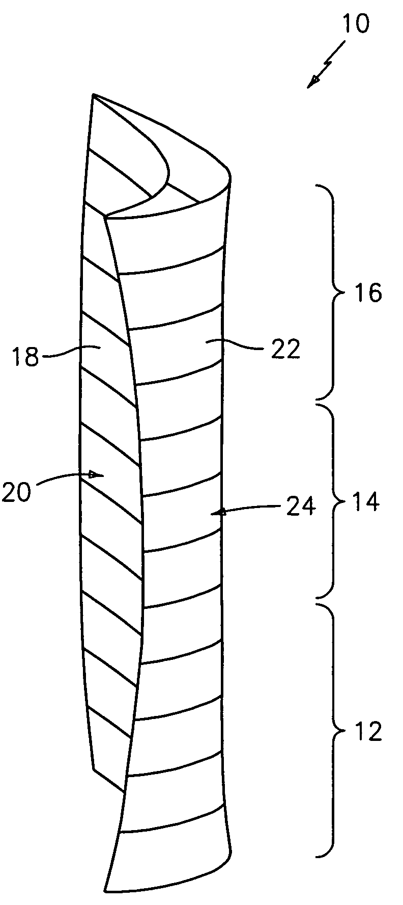
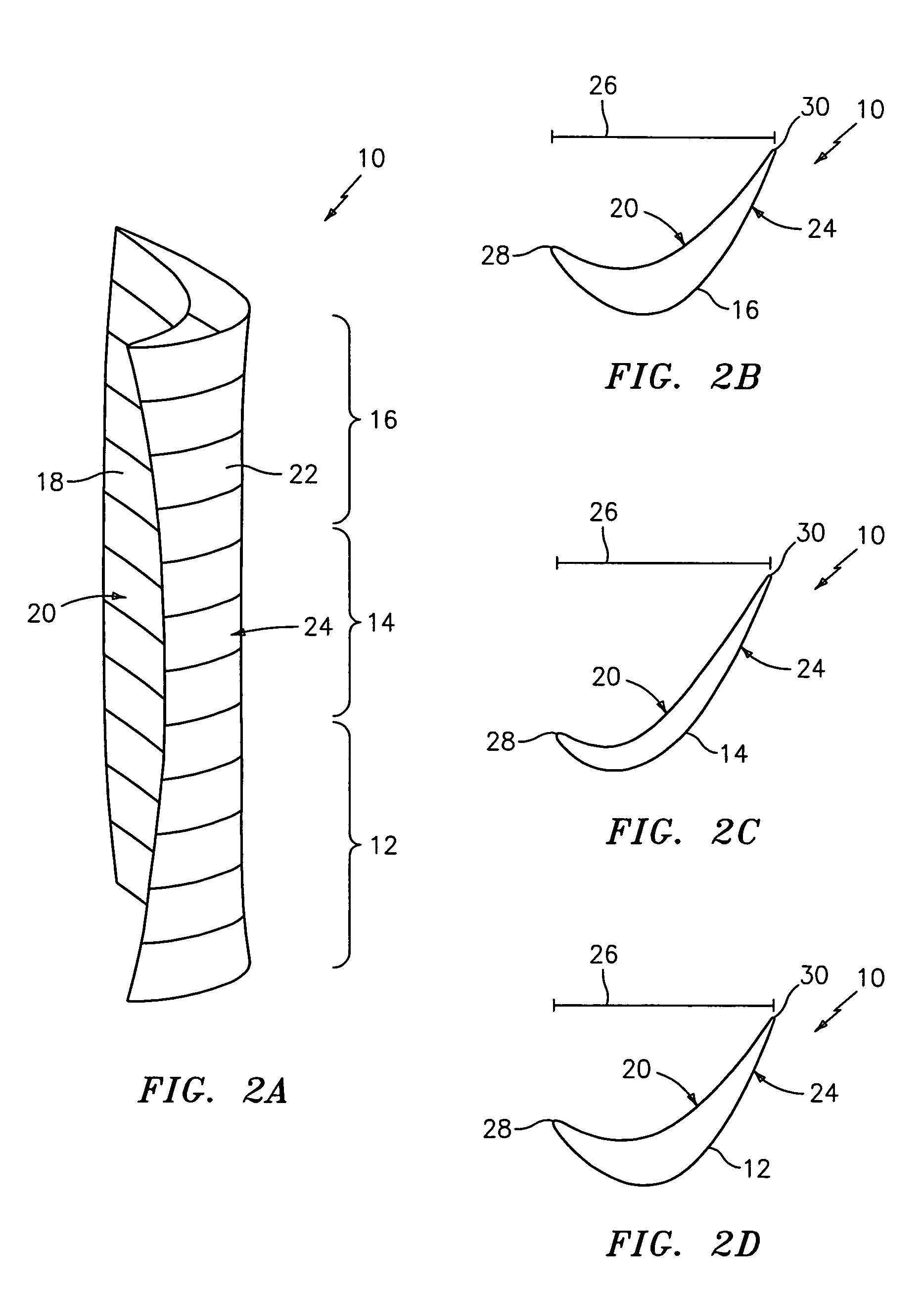
[0034]An airfoil embodying a combination of loading conventions in a single high-lift design specifically to reduce and control the total pressure losses that occur in the working medium fluid passages between airfoils employed in turbomachinery applications is disclosed herein. As will be discussed in greater detail, a high-lift airfoil embodying mixed-loading conventions exhibits the most favorable total pressure loss characteristics possessed by both aft-loaded airfoil and front-loaded airfoil conventions. Moreover, such mixed-loading conventions are capable of more favorably influencing the development of an airfoil surface boundary layer in such applications, as well as the interaction of airfoil surface boundary layers with the endwall boundary layers.

[0035]The high-lift airfoil design(s) of the present invention overcome these performance obstacles using a mixed-loading convention described herein. The high-lift airfoil design(s) embodying a mixed-loading convention of the pr...


PUM


Abstract

A high-lift airfoil embodying a combination of loading conventions in a single design specifically to reduce and control total pressure losses that occur in the flow channels between airfoils employed in turbomachinery applications is disclosed herein. The mixed-loading high-lift airfoil designs embody and exhibit the best total profile and secondary loss characteristics possessed by both aft-loaded airfoil and front-loaded airfoil conventions through controlling the development and interaction of boundary layers forming along the surfaces of the airfoils and the endwalls in such applications. The mixed-loading high-lift airfoil may be utilized in both rotating and non-rotating turbomachinery applications.

Description

FIELD OF USE[0001]The present invention relates generally to airfoils and, more specifically, to a high-lift airfoil design embodying mixed loading conventions.BACKGROUND OF THE INVENTION[0002]Turbomachinery applications generally employ one or more components containing rotating and / or non-rotating airfoils, for example, a compressor or a turbine. When testing the airfoils of such turbomachinery, engineers typically measure a loss of total pressure to gauge the airfoil's performance. Three well-known factors that engender total pressure loss in rows of turbomachinery airfoils are the behavior of the boundary layer along the airfoil surface, the behavior of the boundary layers along the inner and outer diameter end walls to which the airfoil is attached, and the interaction of the airfoil and endwall boundary layers with each other. Current industry practice recognizes the significance and impact of loss control but does not yet fully understand the underlying physics governing the ...

Claims


Application Information

Patent Timeline
Patent Type & Authority Patents(United States)
IPC IPC(8): F04D27/02
CPCF01D5/141F05D2250/71Y10S416/02Y02T50/60
Inventor GROVER, ERIC A.PRAISNER, THOMAS J.
Owner RTX CORP
Learn More