Electrical connector with improved contact

a technology of electric connectors and contact points, applied in the direction of connection contact material, connection fixed connection, coupling device connection, etc., can solve the problem of increasing production costs and achieve the effect of improving grounding or power conta

Active Publication Date: 2010-03-30
HON HAI PRECISION IND CO LTD
View PDF7 Cites 18 Cited by
  • Summary
  • Abstract
  • Description
  • Claims
  • Application Information

AI Technical Summary

Benefits of technology

[0004]In high density current connector, a plurality of conductive contacts transferring signal are arrayed parallel in the housing along an elongated direction. Usually, the distance between adjacent contacts is more and more smaller due to miniaturization based on high density. And contacting portions each are wider than corresponding soldering legs so that the contacting portions can reliably engage with mating contacts of a mating connector and the distance between two adjacent soldering legs are enlarged, thereby avoidance of adjoining the adjacent soldering legs by weld raw materials is obtained. Power contact or grounding contacts might be added to optimize signal transfer or the connector, for example, a current connector disclosed in U.S. Pat. No. D505,919. The connector disclosed is provided with power contacts, which is larger than the signal contacts to transfer a larger current. The power contacts stand beside the signal contacts with a larger distance, which will increase the connector. More, the power contacts must be solely produced, which results in increasing cost of production.
[0007]In order to achieve above-mentioned object, an electrical connector comprises an insulating housing defining a first direction and a plurality of conductive contacts arrayed in the housing along the first direction. The contacts comprises a first type and a second type and each comprises a soldering portion extending out the insulating housing. The soldering portion of the second type is wider than that of the first type and distances between every adjacent soldering portions of the first and second type are the same.

Problems solved by technology

More, the power contacts must be solely produced, which results in increasing cost of production.

Method used


Image

  • Electrical connector with improved contact
  • Electrical connector with improved contact
  • Electrical connector with improved contact

Examples


Embodiment Construction

[0016]Reference will now be made to the drawing figures to describe the preferred embodiment of the present invention in detail.

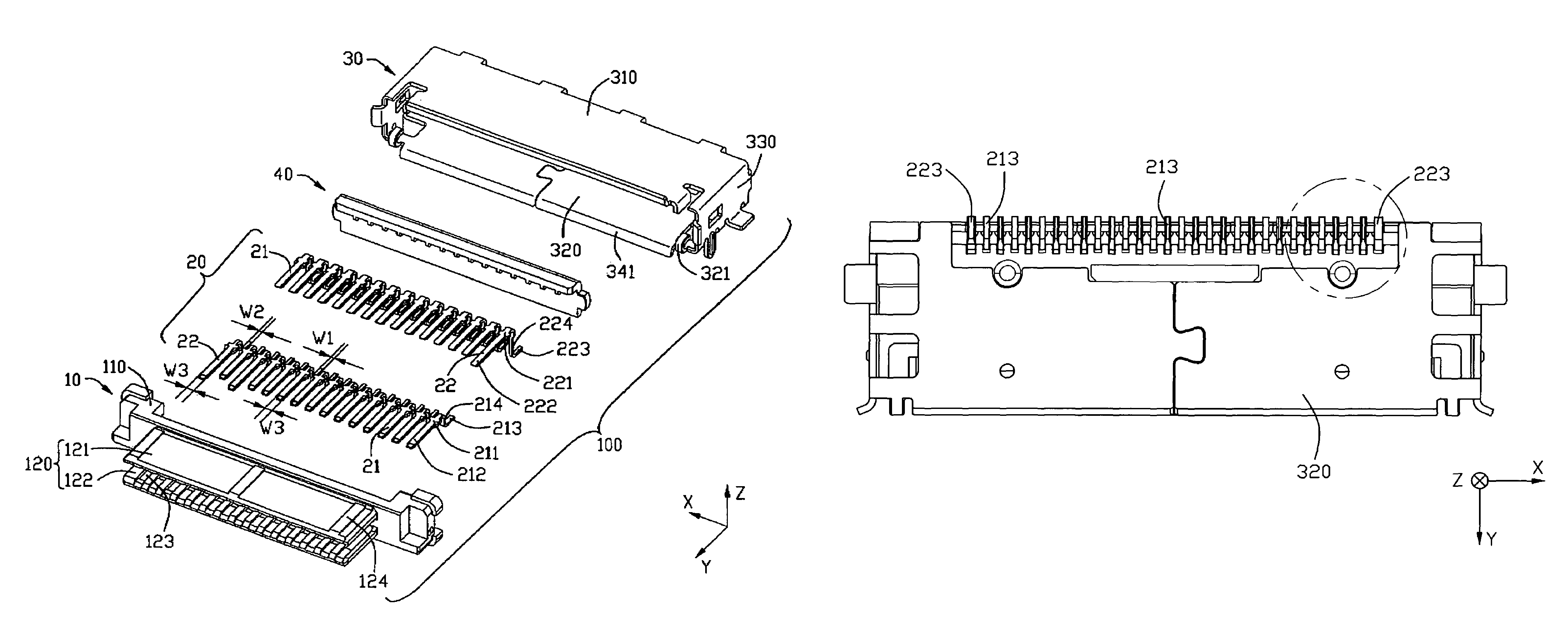
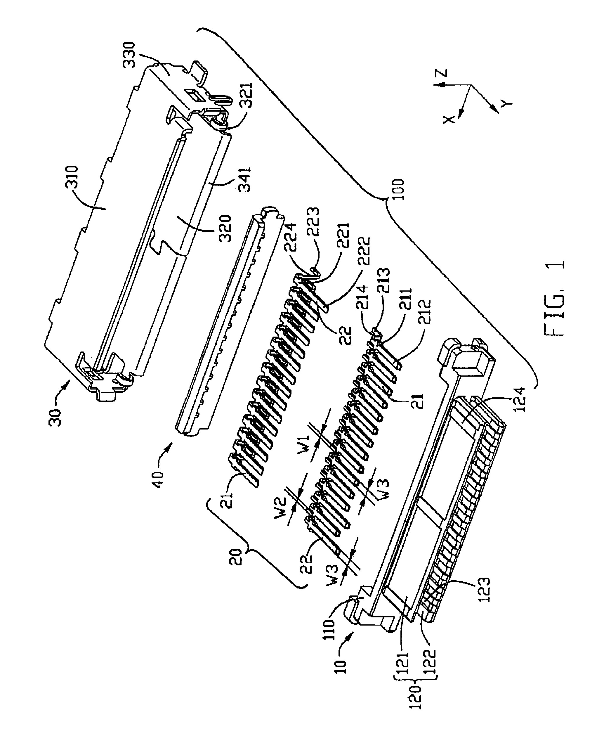
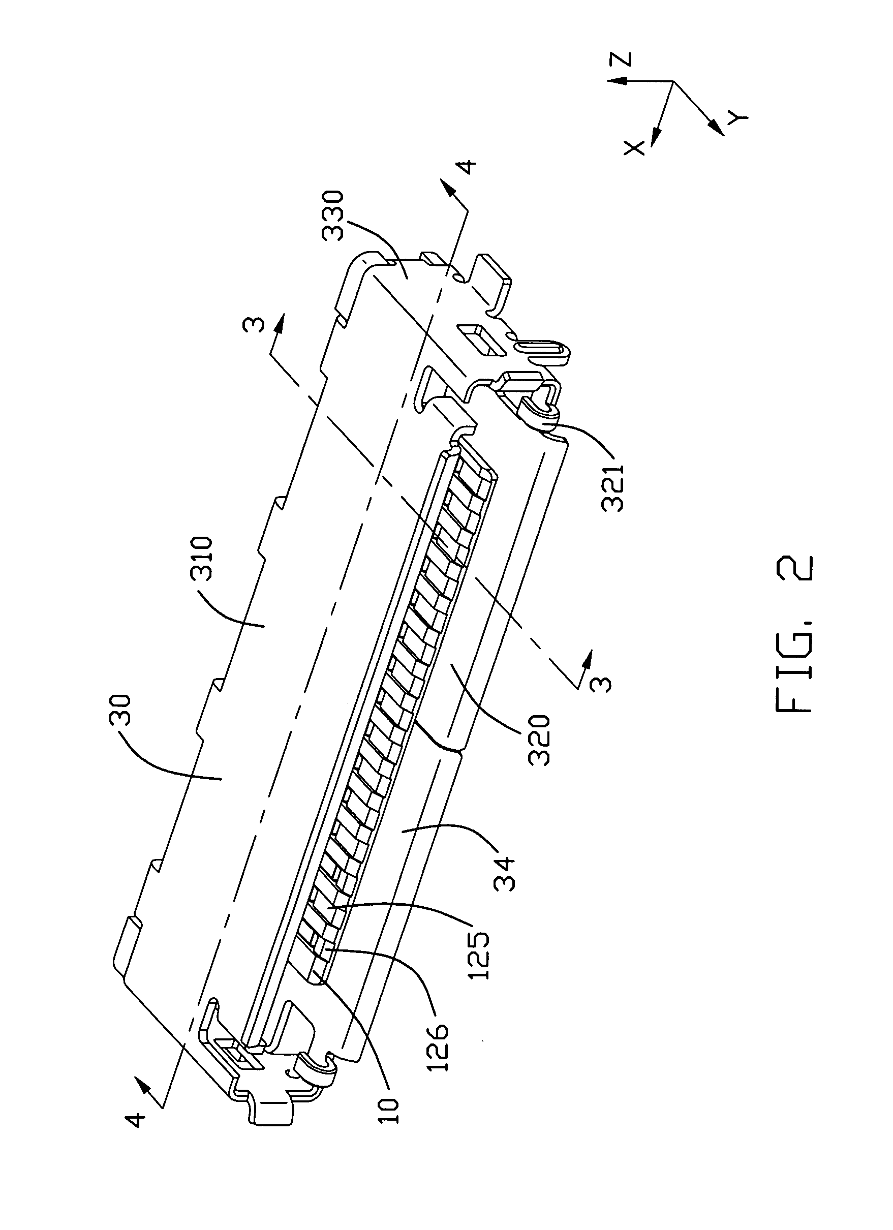
[0017]Referring to FIG. 1, an electrical connector 100 in accordance with the present invention comprises an insulating housing 10 with a plurality of conductive contacts 20 assembled therein. A metal shield 30 is assembled to the housing 10 and a stopper 40 is provided at a rear portion of the housing 10.

[0018]The insulating housing 10 includes an elongated base portion 110 defining a first direction (“X” direction) along the elongated direction and a mating portion 120. The base portion 110 has a front portion and a rear portion in a second direction (“Y” direction) perpendicular to the first direction. The mating portion 120 extends forward from the frond portion of the base portion 110. The mating portion includes an upper tongue 121 and a lower tongue 122 which is in parallel to the upper tongue 121. Two inner surfaces, which are face-to-face, of both ...


PUM


Abstract

An electrical connector includes an insulating housing (1) defining a first direction and a plurality of conductive contacts (20) arrayed in the housing along the first direction. The contacts are divided into a first type and a second type and each includes a soldering portion extending out the insulating housing. The soldering portion of the second type is wider than that of the first type and distances between every adjacent soldering portions of the first and second type are the same.

Description

BACKGROUND OF THE INVENTION[0001]1. Field of the invention[0002]The present invention relates to an electrical connector, especially to an electrical connector with ground contacts or power contacts thereof.[0003]2. Description of Related Art[0004]In high density current connector, a plurality of conductive contacts transferring signal are arrayed parallel in the housing along an elongated direction. Usually, the distance between adjacent contacts is more and more smaller due to miniaturization based on high density. And contacting portions each are wider than corresponding soldering legs so that the contacting portions can reliably engage with mating contacts of a mating connector and the distance between two adjacent soldering legs are enlarged, thereby avoidance of adjoining the adjacent soldering legs by weld raw materials is obtained. Power contact or grounding contacts might be added to optimize signal transfer or the connector, for example, a current connector disclosed in U....

Claims


Application Information

Patent Timeline
Patent Type & Authority Patents(United States)
IPC IPC(8): H01R4/66H01R12/55H01R12/71
CPCH01R43/0256H01R12/725
Inventor LINO, KOICHISHEN, GUO-JIAN
Owner HON HAI PRECISION IND CO LTD
Why Eureka
Try Eureka