
Multiple speed automatic transmission

a multi-speed, automatic transmission technology, applied in mechanical equipment, transportation and packaging, gearing, etc., can solve the problem of providing a large span with at least one excessively large step, and achieve the effect of improving fuel economy and lowering engine speed

Active Publication Date: 2010-03-30
FORD MOTOR CO
View PDF17 Cites 92 Cited by
  • Summary
  • Abstract
  • Description
  • Claims
  • Application Information

AI Technical Summary

Benefits of technology

The transmission achieves superior towing capability and improved highway fuel economy by maintaining similar ratios to a six-speed automatic transmission with an additional low-range gear, reducing engine speeds and enhancing fuel efficiency.

Problems solved by technology

Most transmissions that provide a large span have at least one excessively large step.

Method used


Image

  • Multiple speed automatic transmission
  • Multiple speed automatic transmission
  • Multiple speed automatic transmission

Examples


Embodiment Construction

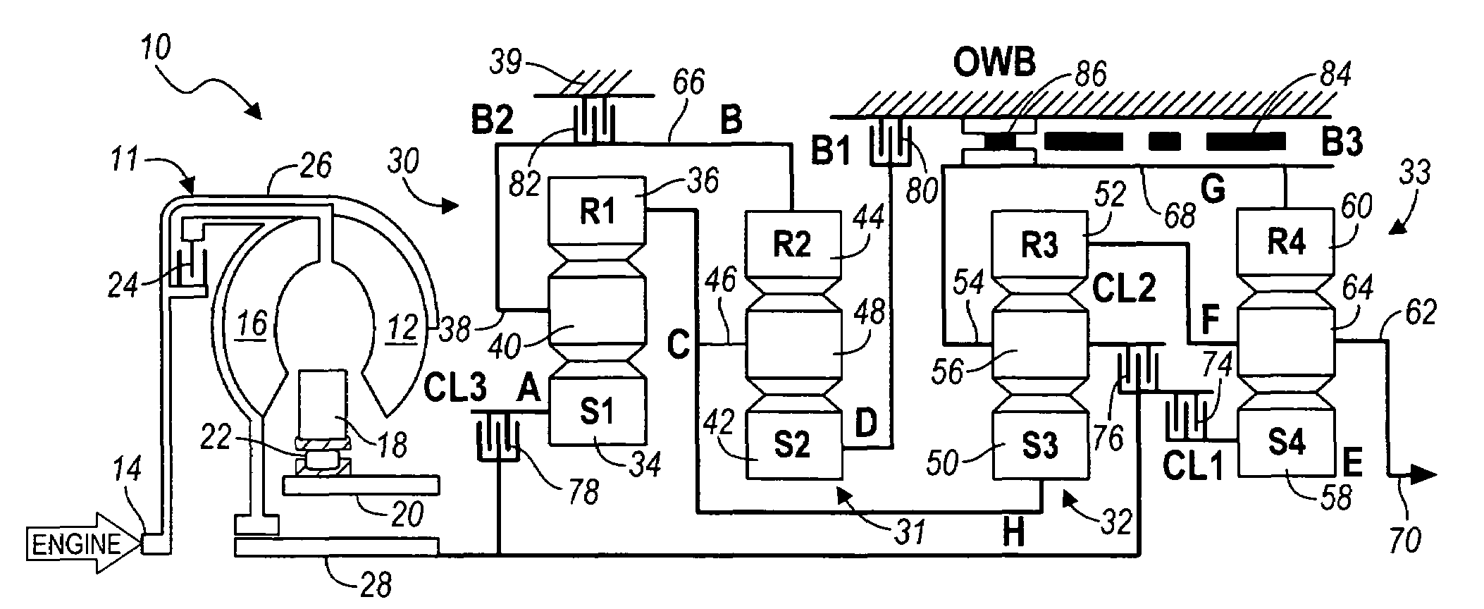
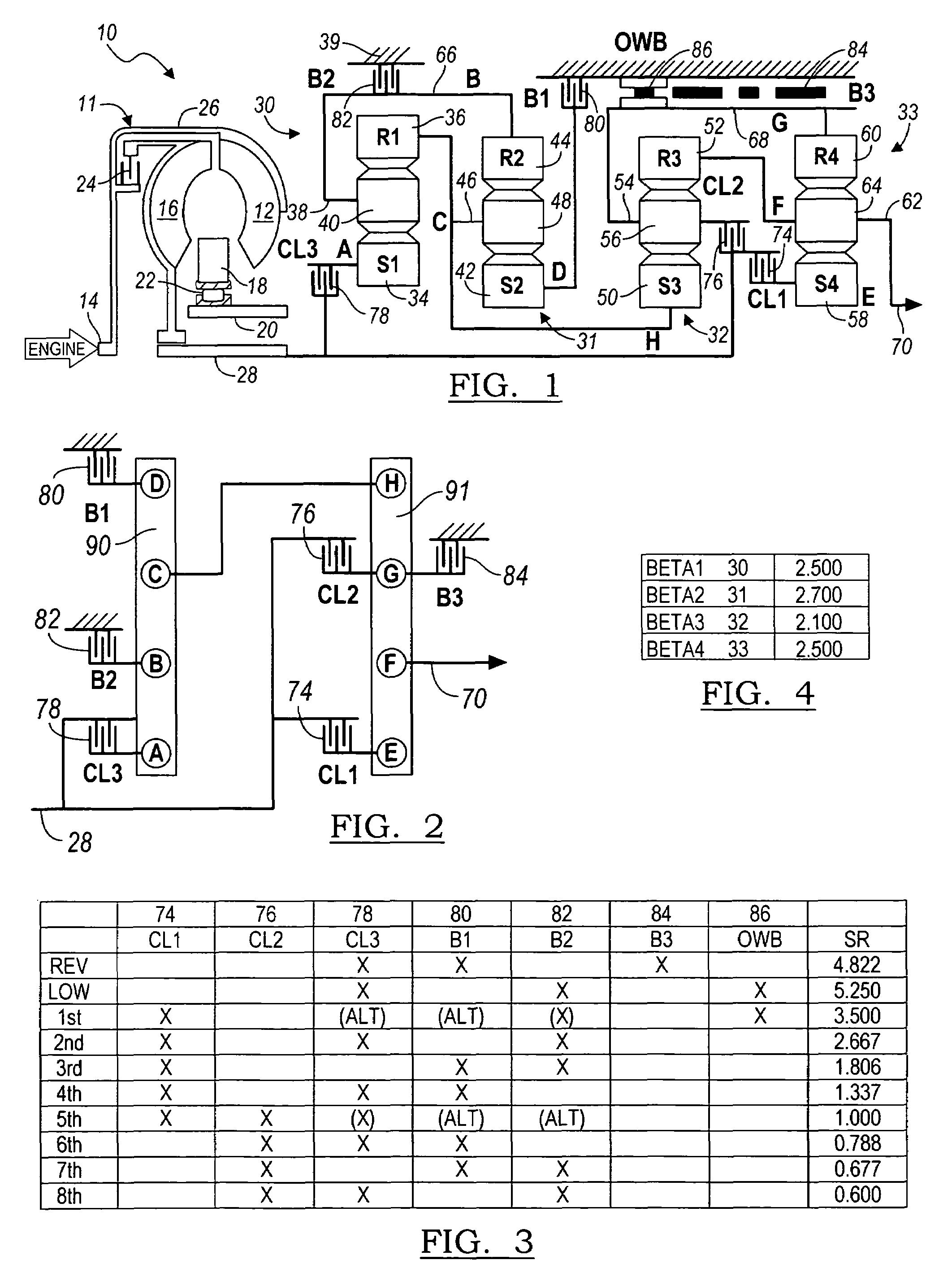
[0025]Referring now to the drawings, there is illustrated in FIG. 1 the kinematic arrangement of an automatic transmission 10. A torque converter includes a bladed impeller wheel 12 connected to the crankshaft 14 of an internal combustion engine, a bladed turbine wheel 16, and a bladed stator wheel 18. The impeller, stator and turbine wheels define a toroidal fluid flow circuit, whereby the impeller is hydrokinetically connected to the turbine. The stator 18 is supported rotatably on a stationary stator sleeve shaft 20, and an overrunning brake 22 anchors the stator to the shaft 20 to prevent rotation of the stator in a direction opposite the direction of rotation of the impeller, although free-wheeling motion in the opposite direction is permitted.

[0026]The torque converter includes a lockup clutch 24 located within the torque converter impeller housing 26. When clutch 24 is engaged, the turbine and impeller are mechanically connected to a transmission input shaft 28; when clutch 2...


PUM


Abstract

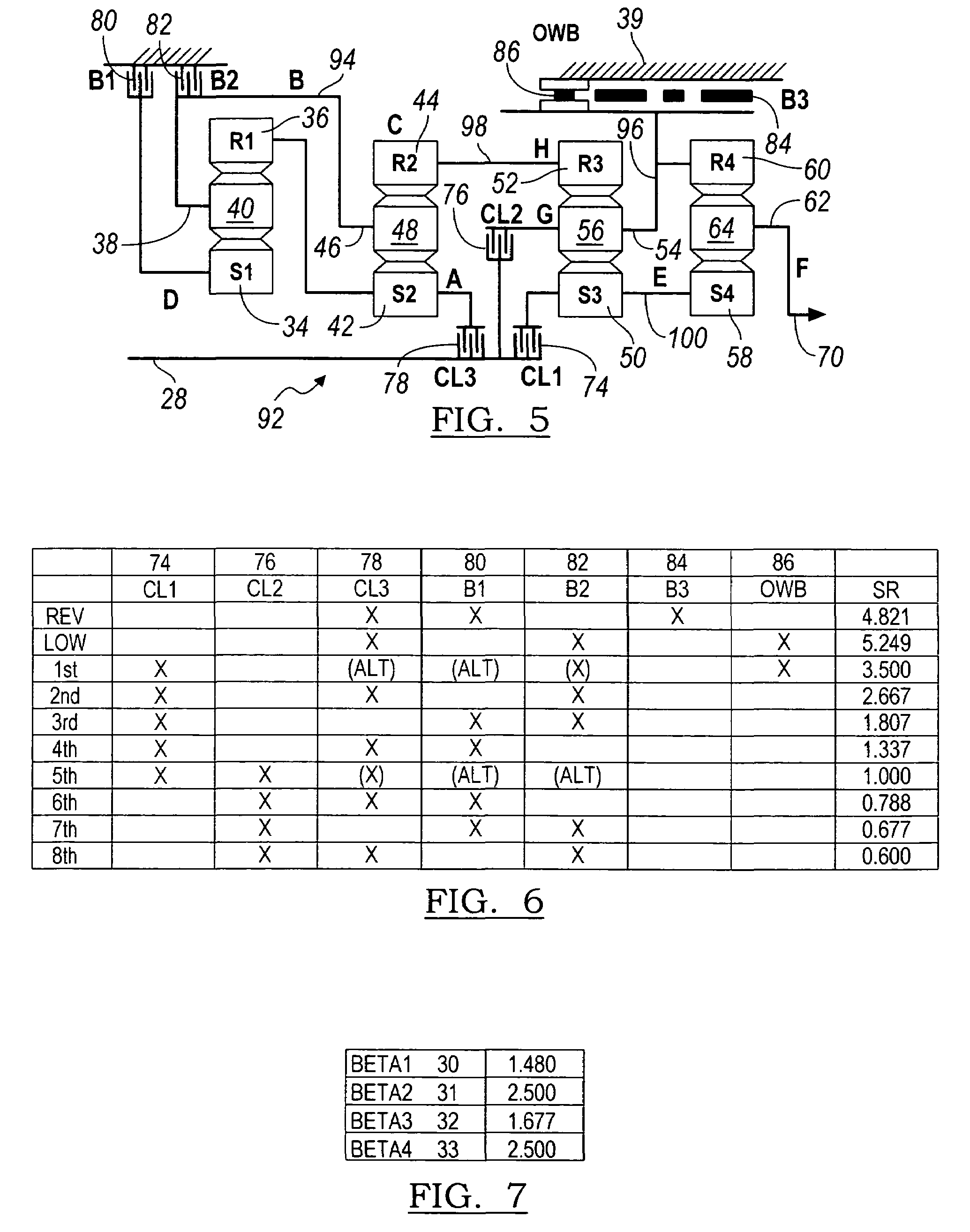
A multiple speed transmission includes an input and output; a first, second, third and fourth planetary gear sets, each gear set including a sun gear, a ring gear, a carrier, and pinions supported on the carrier and meshing with the sun gear and the ring gear; a first epicyclic gearing assembly including the first gear set, the second gear set, a first clutch, a first brake, a second brake, and first, second, third and fourth rotating members, said first clutch being operable to couple said first rotating member to the input, said first brake being operable to hold said fourth rotating member against rotation, and said second brake being operable to hold said second rotating member against rotation; and a second epicyclic gearing assembly including the third gear set, the fourth gear set, a second clutch, a third clutch, a third brake, and fifth, sixth, seventh and eighth rotating members, the third rotating member being secured to the eighth rotating member, said second control clutch being operable to couple said fifth rotating member to the input, said second control clutch being operable to couple said seventh rotating member to the input, said third brake being operable to hold the seventh rotating member against rotation, and said sixth rotating member being secured for rotation to the output.

Description

BACKGROUND OF THE INVENTION[0001]1. Field of the Invention[0002]This invention relates to the field of automatic transmissions for motor vehicles. More particularly, the invention pertains to a kinematic arrangement of gearing, clutches, brakes, and the interconnections among them in a power transmission.[0003]2. Description of the Prior Art[0004]Light trucks have been offered for sale with a variety of optional axle ratios. Customers that plan to tow heavy trailers usually order axles for such trucks that have higher torque ratios in order to get better performance when the vehicle is heavily loaded. Customers that do not plan to tow heavy trailers choose axles with less torque multiplication in order to get better highway fuel economy.[0005]The steeper axle ratios improve vehicle launch capability when loaded, but reduce fuel economy even when the vehicle is unloaded. Providing multiple axle ratios adds complexity at the vehicle assembly plant. Operators of light truck having 4×4 ...

Claims


Application Information

Patent Timeline
Patent Type & Authority Patents(United States)
IPC IPC(8): F16H3/62
CPCF16H3/66F16H2200/0026F16H2200/006F16H2200/0065F16H2200/2012F16H2200/2048F16H2200/2097F16H3/666
Inventor BALDWIN, REID A.
Owner FORD MOTOR CO
Learn More