Operating switch unit for use in automotive vehicle
a technology for automotive vehicles and switches, applied in the field of switches, can solve the problems of insufficient effectiveness of technique (1) and difficulty in intercepting such reflected light, and achieve the effect of enhancing the ornamental effect of the switch unit and minimizing the errors in selecting switches to be operated
- Summary
- Abstract
- Description
- Claims
- Application Information
AI Technical Summary
Benefits of technology
Problems solved by technology
Method used
Image
Examples
first embodiment
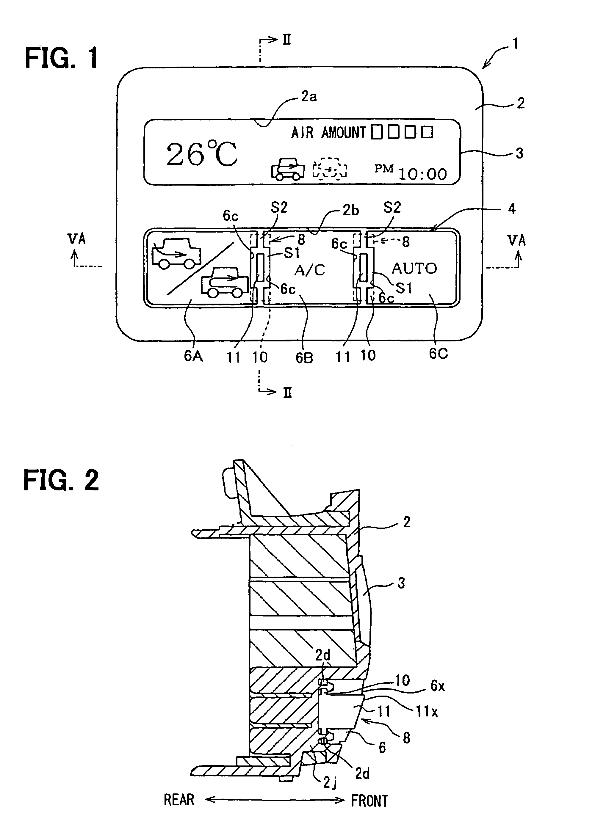
[0032]the present invention will be described with reference to FIGS. 1-12. FIG. 1 shows a switch unit 1 for operating an air-conditioner mounted on an automotive vehicle. The switch panel 1 is contained in a casing 2. The switch panel 1 includes a liquid crystal display panel (LCD) 3 and a switch unit 4. The LCD panel 3 is exposed to outside from a window 2a of the switch panel 1, and the switch unit 4 is installed in a window 2b of the switch panel 1.
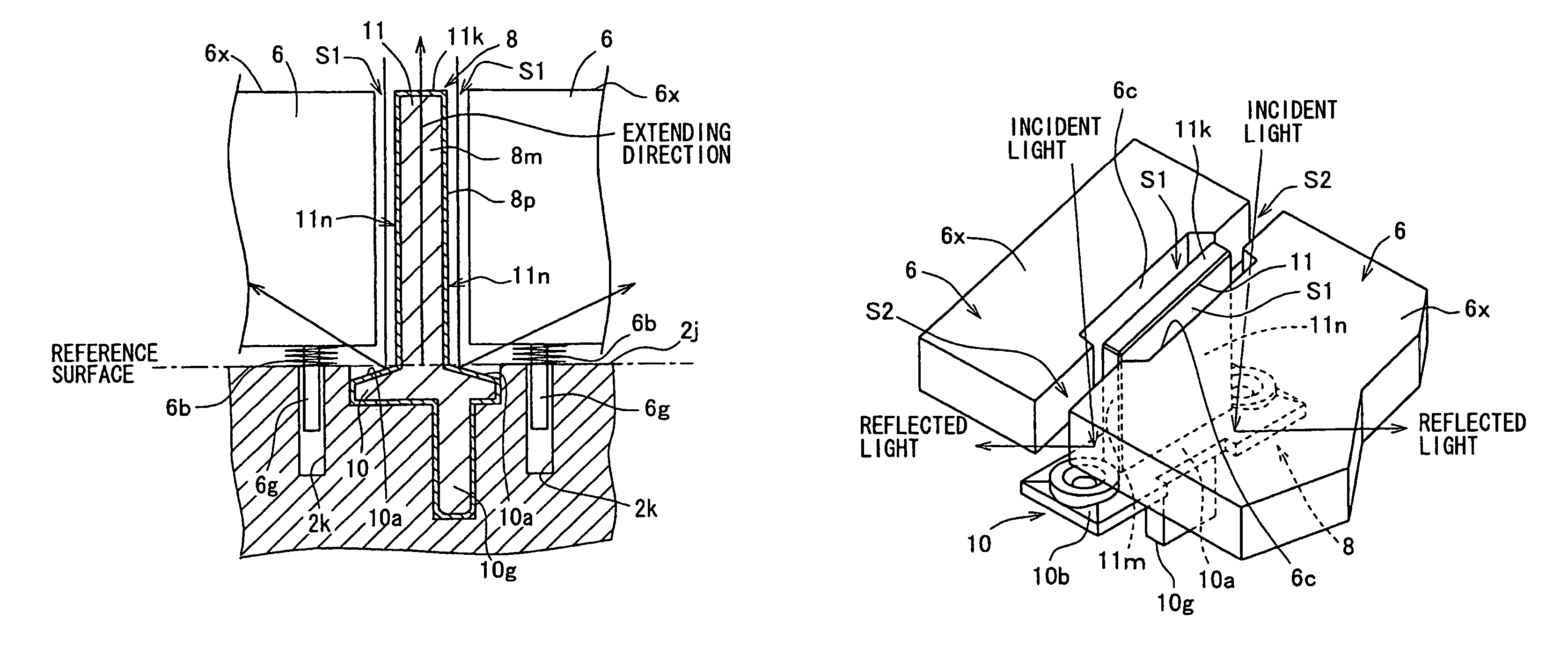
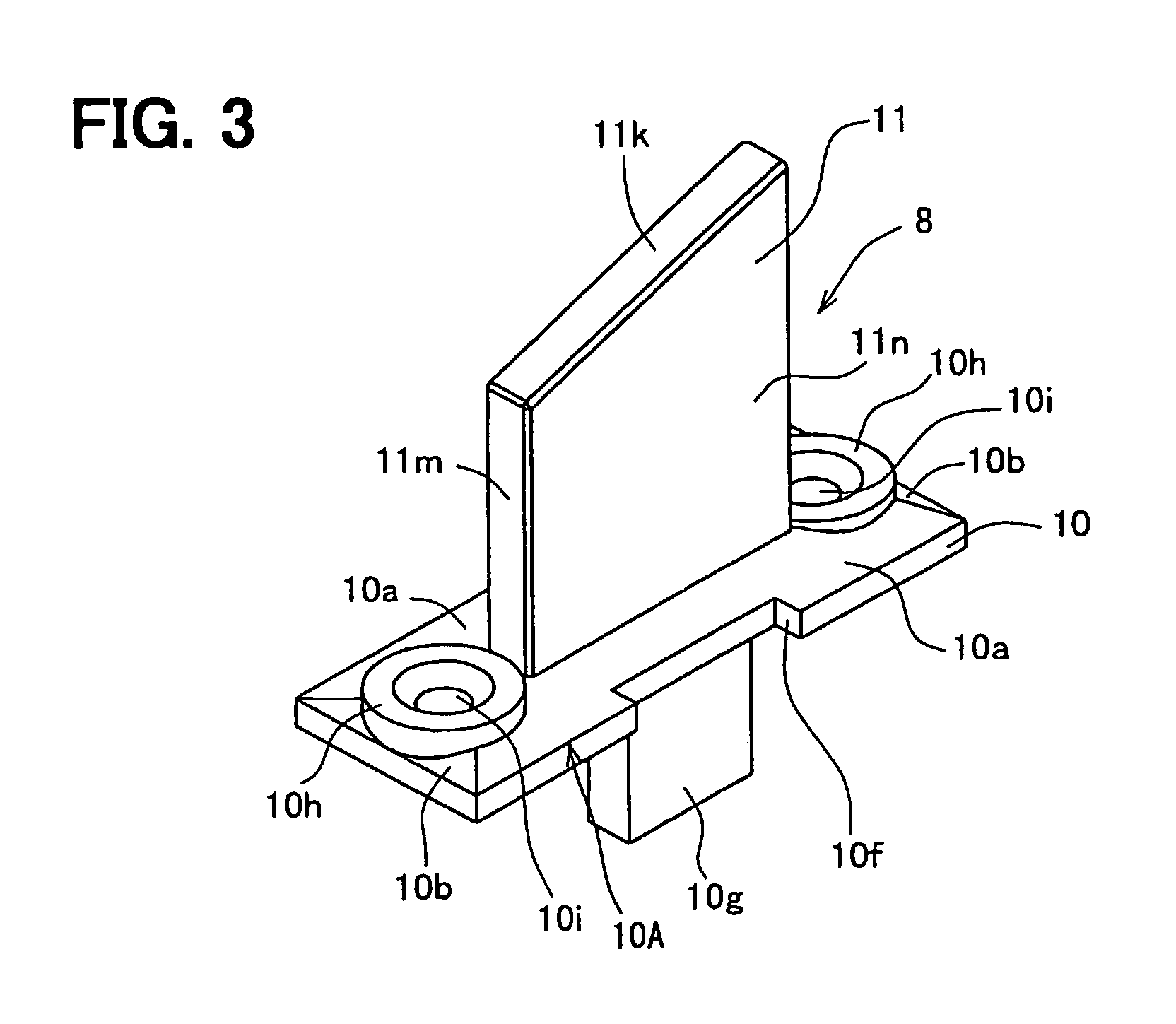
[0033]The switch unit 4 includes three switches 6 (6A, 6B and 6C) and two ornamental members 8 disposed between switches 6. The switch 6A is a switch for switching between outside air and inside air. The switch 6B is a switch for turning on and off the air-conditioner. The switch 6C is a switch for switching between an automatic operation and a manual operation. By pushing these switches, operation of the air-conditioner is controlled by a user (a passenger or a driver). On the LCD panel 3, temperature in the passenger compartment, wh...
second embodiment
[0048]the present invention will be described with reference to FIGS. 13-15. In this embodiment, the switch panel 1′ includes a dial 205 for adjusting air amount. An ornamental member 308 is disposed around the dial 205. As shown in FIG. 14, the ornamental member 208 is composed of a base portion 210 and a cylindrical extending portion 211 extending from the base portion 210. The base portion 210 has a sloped surface 210a declining from the foot of the extending portion 211 toward the outer periphery of the base portion 210.
[0049]As shown in FIG. 15, an outer surface of the ornamental member 208 including its sloped surface 210a is covered with an ornamental light-reflecting layer 208p. The ornamental light-reflecting layer 208p is formed on a plastic molded body 208m. The dial 205 is inserted into the ornamental member 208 from its bottom opening. A circular projection 210e formed on an inner wall of the base portion 210 engages with a groove formed on an outer periphery of the dia...
third embodiment
[0050]the present invention will be described with reference to FIG. 16. In this embodiment, an ornamental member 308 constitutes a push button switch, and a front panel 306 constitutes a neighboring member. The ornamental member 208 is composed of a base portion 310 and an extending portion 311 extending from the base portion 310. A front surface of the base portion 310 is a sloped surface 310a. An outer surface of a plastic molded body 308m including the sloped surface 310a is entirely covered with an ornamental light-reflecting layer 308p. The front panel 306 has a hole 306h through which the extending portion 311 of the ornamental member 308 extends. A gap S is formed between the extending portion 311 and the hole 306h. Since light reaching the sloped surface 310a through the gap S is reflected thereon, the reflected light reaching eyes of the user is suppressed.
PUM
 Abstract
Description
Claims
Application Information
 - R&D
- Intellectual Property
- Life Sciences
- Materials
- Tech Scout
- Unparalleled Data Quality
- Higher Quality Content
- 60% Fewer Hallucinations
Browse by: Latest US Patents, China's latest patents, Technical Efficacy Thesaurus, Application Domain, Technology Topic, Popular Technical Reports.
© 2025 PatSnap. All rights reserved.Legal|Privacy policy|Modern Slavery Act Transparency Statement|Sitemap|About US| Contact US: help@patsnap.com


