Method and apparatus for RF input coupling for inductive output tubes and other emission gated devices

a technology of inductive output tube and input coupling, which is applied in the direction of traveling-wave tube, amplifier with semiconductor device/discharge tube, amplifier with transit-time effect, etc., and can solve problems such as preventing substantial larger bandwidths from being achieved

Active Publication Date: 2010-03-30
L3 TECH INC
View PDF11 Cites 7 Cited by
  • Summary
  • Abstract
  • Description
  • Claims
  • Application Information

AI Technical Summary

Problems solved by technology

Practical limits on the loop size prevent substantially larger bandwidths from being achieved.

Method used


Image

  • Method and apparatus for RF input coupling for inductive output tubes and other emission gated devices
  • Method and apparatus for RF input coupling for inductive output tubes and other emission gated devices
  • Method and apparatus for RF input coupling for inductive output tubes and other emission gated devices

Examples


Embodiment Construction

[0029]The invention provides improved instantaneous bandwidth of the input circuit of an IOT or other density-modulated device. In the detailed description that follows, like numbers are used to describe like elements illustrated in one or more of the figures.

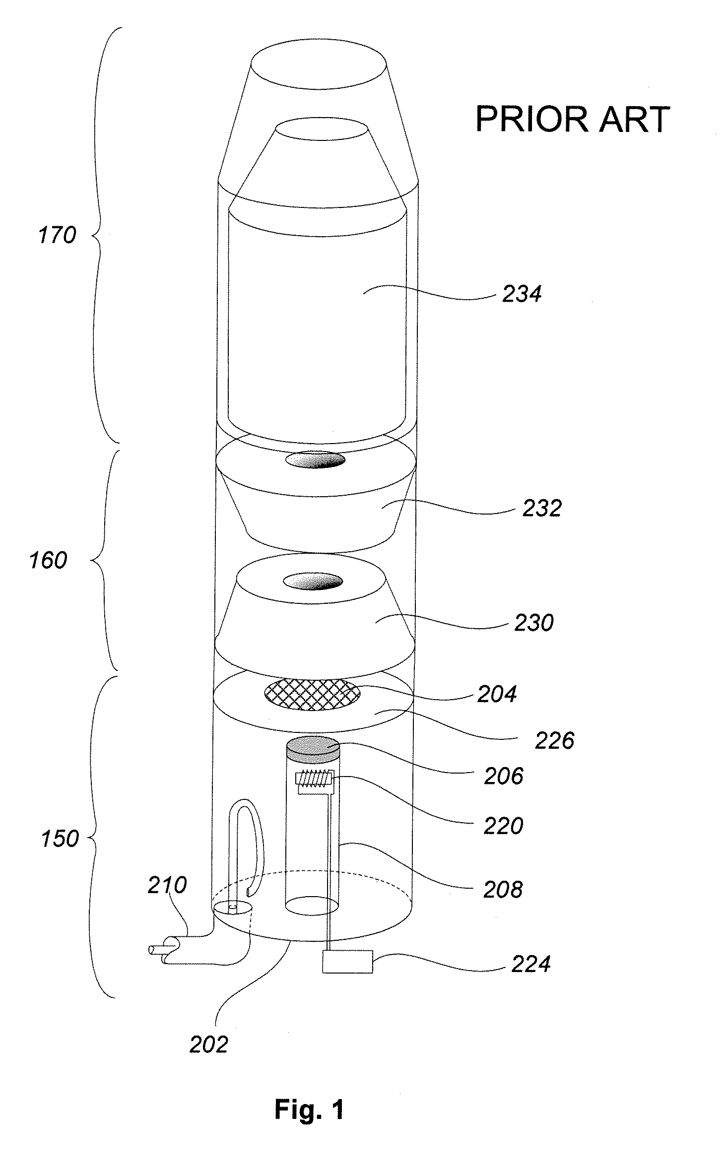
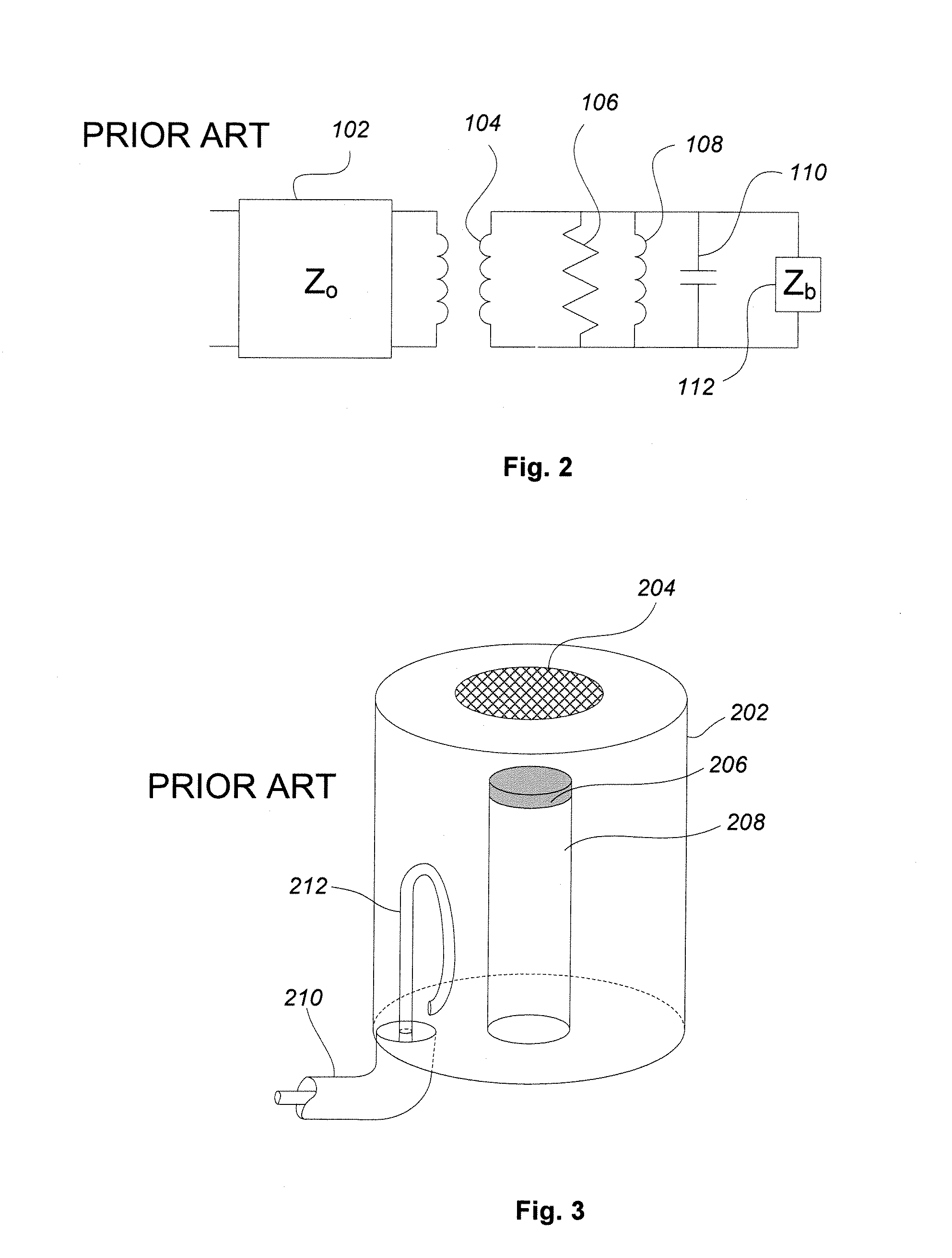
[0030]FIG. 1 is a schematic drawing of an exemplary IOT, typical of the prior art. The IOT includes three major sections, including an electron gun 150, a tube body 160, and a collector 170. The electron gun 150, shown in more detail in FIG. 3, provides an axially directed electron beam that is density modulated by an RF signal. Now returning to FIG. 1, the electron beam passes through a first drift tube 230 and a second drift tube 232 and then passes into an inner structure 234 inside the collector 170 that collects the spent electron beam. The electron gun further includes a cathode 206 with a closely spaced control grid 204. The cathode is disposed at the end of a cathode support structure 208 that includes an internal heate...


PUM


Abstract

An input circuit of a microwave amplification tube achieves improved instantaneous bandwidth. By directly coupling the transmission line carrying a modulating radio frequency signal to a control grid, a low-Q input circuit is created that increases the fractional bandwidth of the system. A resonant cavity may be used to generate a voltage across the gap between the cathode and the control grid. Alternative geometries are presented whereby the electron beam is emitted from a cathode connected either to the center conductor of the transmission line or to the outer conductor of the transmission line. Alternatively, the electric field of the radio-frequency signal propagating through the transmission line may be used to create a voltage across the gap between the cathode and the control grid without using a resonant cavity. Likewise, alternative geometries are presented by which the electron beam is emitted from a cathode connected either to the center conductor or to the outer conductor of the transmission line.

Description

RELATED APPLICATION DATA[0001]This application claims the benefit, pursuant to 35 U.S.C. § 119(e), of U.S. provisional application Ser. No. 60 / 867,756, filed Nov. 29, 2006.BACKGROUND OF THE INVENTION[0002]1. Field of the Invention[0003]The present invention relates to microwave amplification tubes, such as an inductive output tube (IOT), and, more particularly, to an input circuit for an IOT or other emission-gated device providing improved instantaneous bandwidth.[0004]2. Description of Related Art[0005]It is well known in the art to utilize a linear beam device, such as a klystron or traveling wave tube amplifier, to generate or amplify a high-frequency RF signal. Such a device generally includes an electron-emitting cathode and an anode spaced therefrom. The anode includes a central aperture, and by applying a high voltage potential between the cathode and anode, electrons may be drawn from the cathode surface and directed into a high-power beam that passes through the anode aper...

Claims


Application Information

Patent Timeline
Patent Type & Authority Patents(United States)
IPC IPC(8): H01J25/02
CPCH01J25/34H03F3/56H03F3/58
Inventor KIRSHNER, MARK FREDERICKKOWALCZYK, RICHARD DONALDWILSEN, CRAIG BISSET
Owner L3 TECH INC
Why Eureka
Try Eureka