Liquid crystal display with transmissive and reflective regions comprising a first alignment film having different alignments in the transmissive and reflective regions and a second alignment film with a single alignment

a liquid crystal display and transmissive region technology, applied in non-linear optics, instruments, optics, etc., can solve the problems of reducing the contrast and brightness of the reflective display, the transmission vs. voltage curve of the transmissive region is not consistent with the reflectance vs. voltage curve of the reflective region, and the difficulty of the array and driving method to achieve high contrast and color quality, etc., to achieve the effect of avoiding complexity and difficulty in the array and driving method

Active Publication Date: 2010-03-30
AU OPTRONICS CORP
View PDF22 Cites 2 Cited by
  • Summary
  • Abstract
  • Description
  • Claims
  • Application Information

AI Technical Summary

Benefits of technology

[0016]Yet another aspect of the invention is to provide a manufacturing method of a transflective LCD panel that uses the single cell gap design and uses a photo-polymer to form an alignment film. The alignment film results in different alignment effects on the liquid crystal molecules in the transmissive and reflective regions after photo-polymerization.
[0022]Therefore, the disclosed manufacturing method of the transflective LCD has the following advantages: (1) it uses a single cell gap design to avoid the complexity in the process for the dual cell gap design; (2) it uses a single cell gap design and a single control circuit to control the transmissive and reflective regions, avoiding the complexity and difficulty in the array and driving method; (3) it can use the IPS technique and, therefore, the transflective LCD thus formed essentially has a wide solid angle without employing any additional technique; and (4) it reduces the production cost.

Problems solved by technology

However, it is more difficult for the reflective display to achieve high contrast and high color quality (particularly full colors) at high resolutions.
Moreover, when the environmental light source provides insufficient light, the contrast and brightness of the reflective display are greatly reduced.
However, when the cell gaps of the transmissive region and the reflective region are the same, the transmittance vs. voltage curve of the transmissive region is not consistent with the reflectance vs. voltage curve of the reflective region.
This may increase the complexity and difficulty in the array and the driving method.
However, designing dual cell gaps for the liquid crystal cells will encounter the problems of a complicated manufacturing process and difficulty in controls.
One cannot obtain ideal display effects by simply attaching a transflective film on the display.

Method used


Image

  • Liquid crystal display with transmissive and reflective regions comprising a first alignment film having different alignments in the transmissive and reflective regions and a second alignment film with a single alignment
  • Liquid crystal display with transmissive and reflective regions comprising a first alignment film having different alignments in the transmissive and reflective regions and a second alignment film with a single alignment

Examples


Embodiment Construction

[0026]The present invention will be apparent from the following detailed description, which proceeds with reference to the accompanying drawings, wherein the same references relate to the same elements.

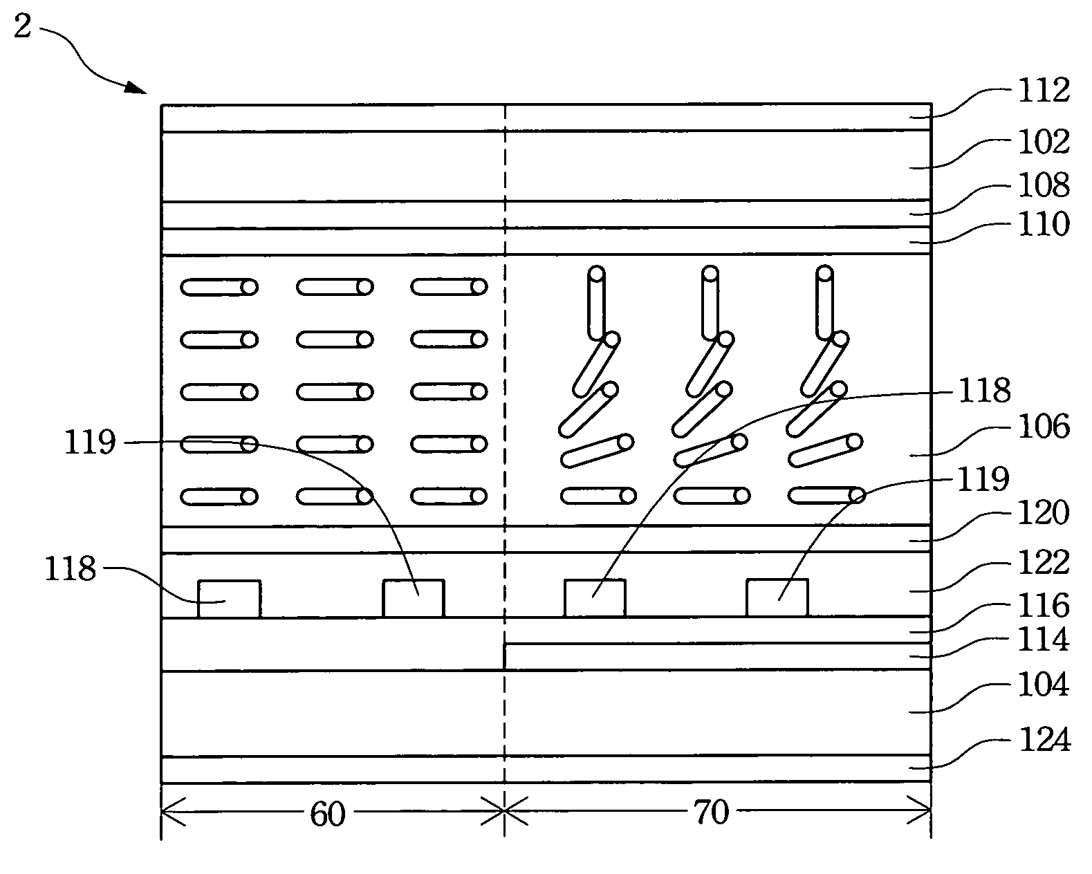
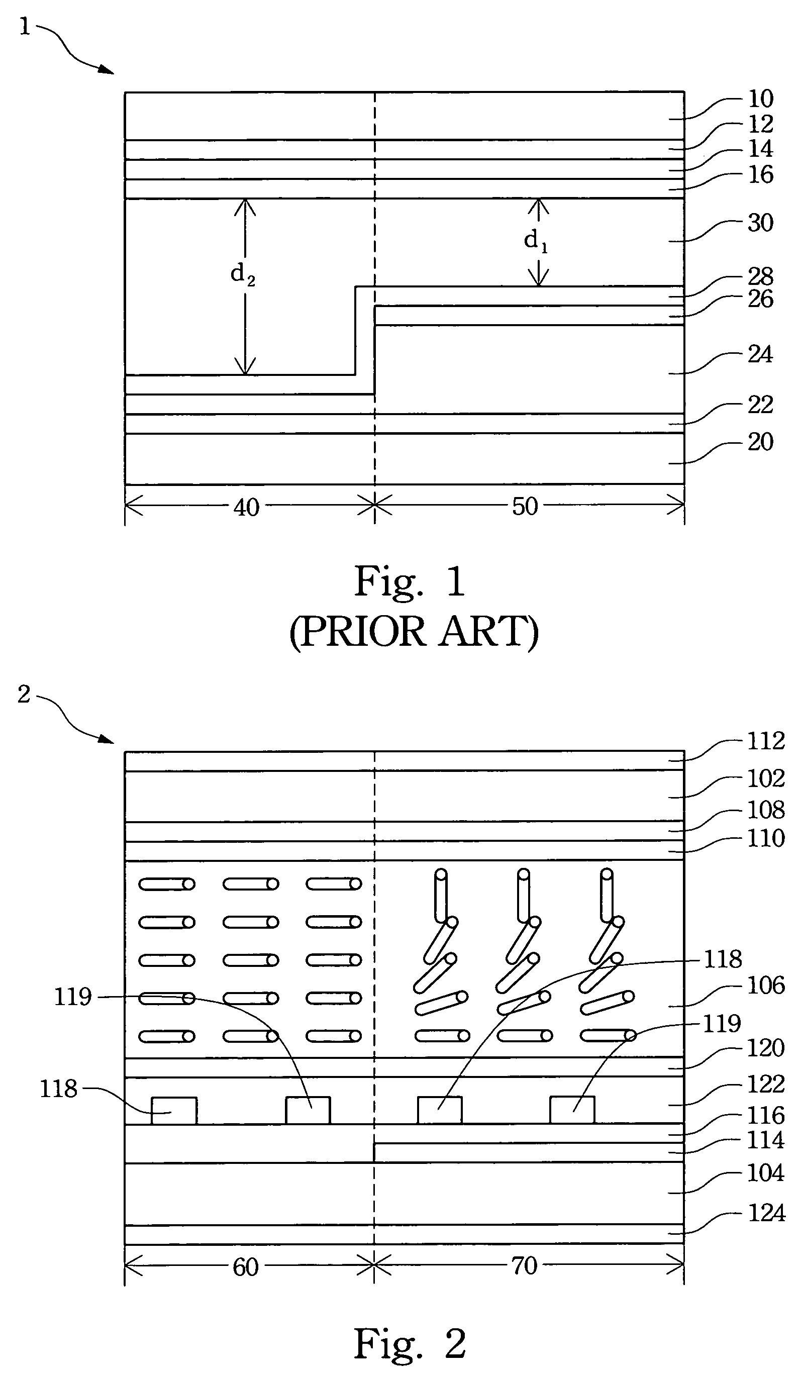
[0027]With reference to FIG. 2, a transflective display panel 2 has a transmissive region 60 and a reflective region 70. The transflective display panel 2 further contains a pair of parallel upper substrate 102 and lower substrate 104, and a liquid crystal layer 106 filled in the gap between the upper substrate 102 and the lower substrate 104. The inner surface of the upper substrate 102, i.e., the one facing the liquid crystal layer 106, is coated with a color filter 108 and a first alignment film 110. The color filter 108 includes an array of red, blue, and green color films and a black matrix film. The outer surface of the upper substrate 102 is coated with a first polarization film 112. The upper substrate 102 and the lower substrate 104 are transparent substrates, such as glass s...


PUM

PropertyMeasurementUnit
angleaaaaaaaaaa
large-angle alignmentaaaaaaaaaa
electric fieldaaaaaaaaaa

Abstract

A liquid crystal display with transmissive region and reflective region is provided. The display comprises an upper substrate and a lower substrate, which is settled in parallel with the upper substrate. A reflective layer is located on the reflective region of the lower substrate and an insulation layer covers the reflective layer and the lower substrate. Positive and negative driving electrodes are chiastically settled on the insulation layer. A first alignment film is positioned on the inner surface of the upper substrate, and the alignments of the first alignment film on the transmissive region and reflective region are different. A second alignment film covers the insulation layer, the positive and negative electrodes. A liquid crystal layer is located between the first alignment film and the second alignment film.

Description

RELATED APPLICATIONS[0001]The present application is based on, and claims priority from, Taiwan Application Serial Number 94128814, filed Aug. 23, 2005, the disclosure of which is hereby incorporated by reference herein in its entirety.BACKGROUND OF THE INVENTION[0002]1. Field of Invention[0003]The invention relates to the production method of a liquid crystal display (LCD) and, in particular, to the manufacturing method of a transflective LCD.[0004]2. Related Art[0005]Opto-electronic technologies have recently made tremendous progress, pushing the rapid development in liquid crystal displays (LCD) in the digital era. The LCD has the advantages of high picture quality, small volume, light weight, low driving voltage and power consumption. Therefore, they are widely used in personal digital assistants (PDA), mobile phones, camcorders, notebook computers, desktop displays, vehicle displays, and projection televisions. They have replaced the conventional cathode ray tubes (CRT) and bec...

Claims


Application Information

Patent Timeline
Patent Type & Authority Patents(United States)
IPC IPC(8): G02F1/1335G02F1/1337G02F1/1343
CPCG02F1/133753G02F1/133788G02F1/134363G02F2001/133757G02F2001/133773G02F1/133773G02F1/133757
Inventor LIN, TZU-YUANCHIANG, CHUN-HUNGHSIEH, FU-CHENGWU, PO-CHANGHUANG, REN-HUNGWU, JIN-JEICHANG, CHIH-MINGCHEN, PO-LUN
Owner AU OPTRONICS CORP
Why Eureka
Try Eureka