
Two-dimensional optical CDMA system, PN coded wavelength/time encoder and decoder therein, and method of encoding/decoding

a two-dimensional optical and cdma technology, applied in the field of optical code division multiple access (ocdma) system, can solve the problems of limited code number, limited created code number, and inability to secure the subscriber number, and achieve the effect of increasing the code number to be used

Inactive Publication Date: 2010-03-30
ELECTRONICS & TELECOMM RES INST
View PDF32 Cites 9 Cited by
  • Summary
  • Abstract
  • Description
  • Claims
  • Application Information

AI Technical Summary

Benefits of technology

The present invention provides an OCDMA system that sequentially encodes and decodes data bits to create matrix type codes using modified PN sequences with stuff bits. The system includes a base station and multiple user terminals, each containing an encoder and decoder. The encoder includes time domain encoding means and optical modulation means, while the decoder includes wavelength domain encoding means, time domain decoding means, and threshold determination means. The system can remove MAI among users and increase the number of code bits. The invention also provides a method of encoding and decoding data bits using complementary codes to prevent generation of MAI. The system and method can improve data transmission and reduce interference between users.

Problems solved by technology

Also, since the encoding and decoding are performed in the one-dimensional wavelength domain, the code number is limited.
However, the proposed system has disadvantages in that the created code number is limited and, furthermore the subscriber number cannot be secured since two codes are distributed to a single subscriber.
However, the prior art system has disadvantage in that MAI cannot be completely removed therefrom due to inherent characteristics of the barker code adopted in the time domain.

Method used


Image

  • Two-dimensional optical CDMA system, PN coded wavelength/time encoder and decoder therein, and method of encoding/decoding
  • Two-dimensional optical CDMA system, PN coded wavelength/time encoder and decoder therein, and method of encoding/decoding
  • Two-dimensional optical CDMA system, PN coded wavelength/time encoder and decoder therein, and method of encoding/decoding

Examples


Embodiment Construction

[0030]Now, preferred embodiments of the present invention will be described in detail with reference to the annexed drawings. In the drawings, the same or similar elements are denoted by the same reference numerals even though they are depicted in different drawings.

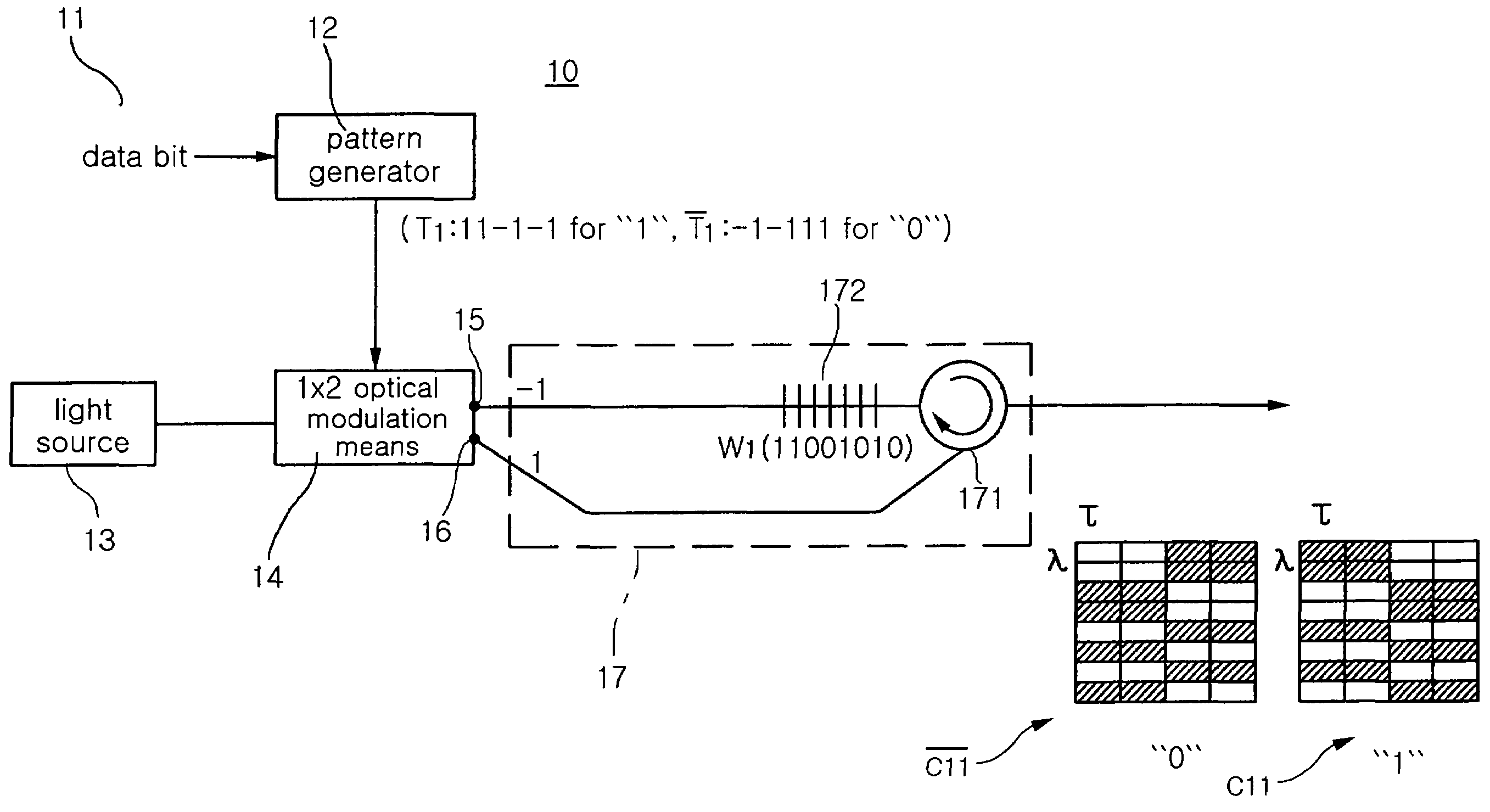
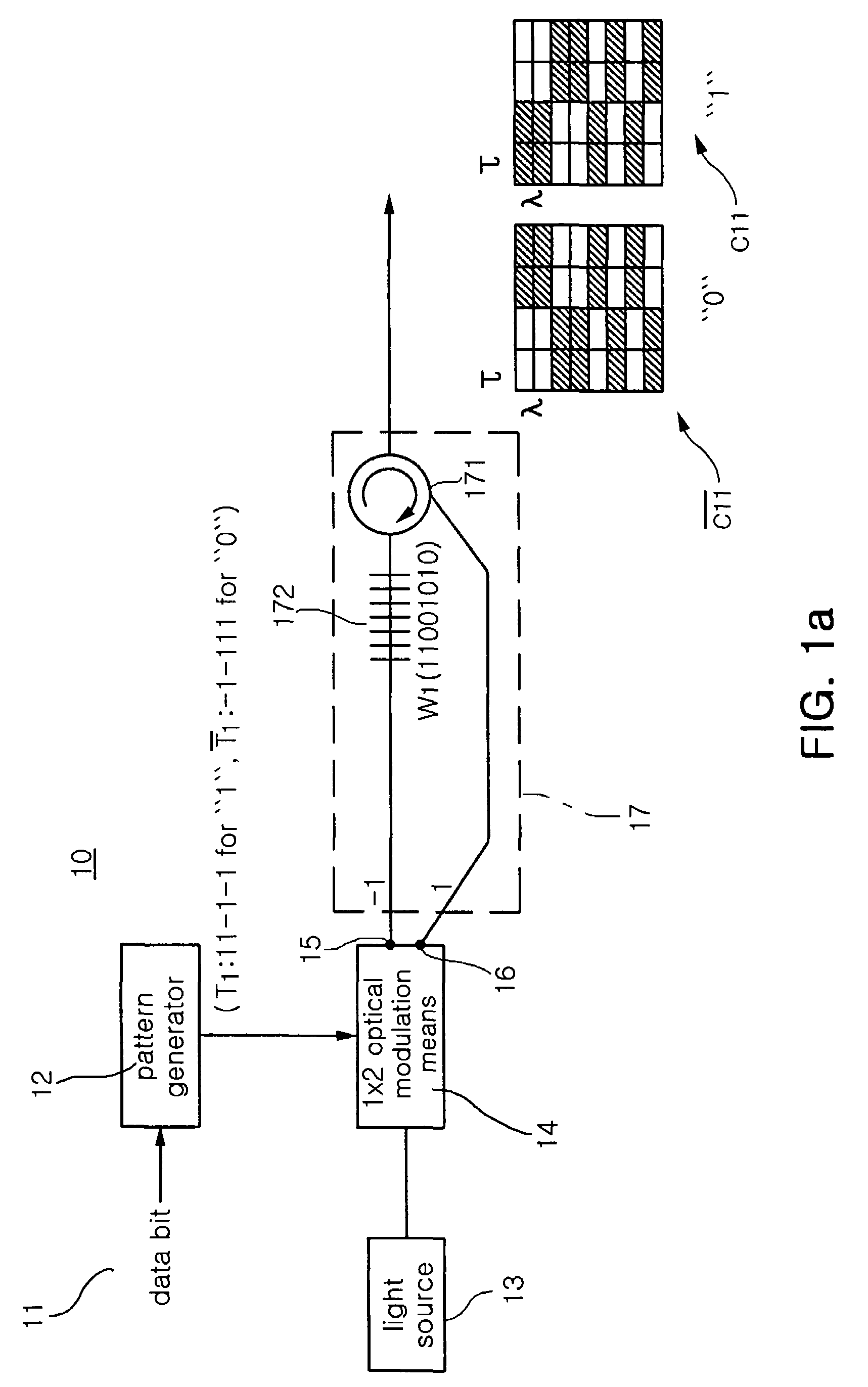
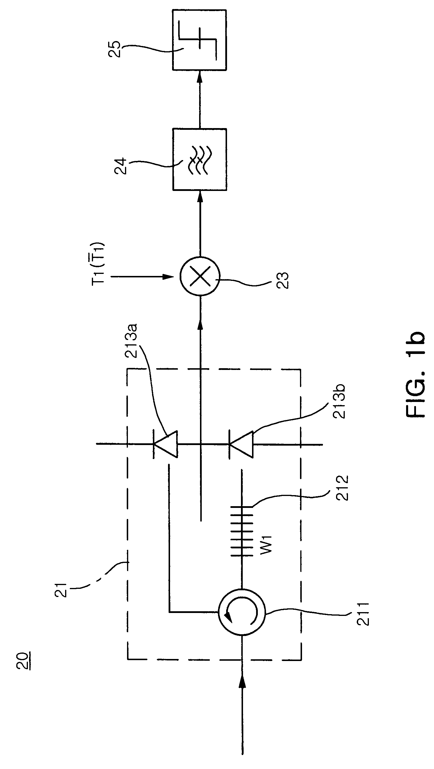
[0031]FIG. 1a and FIG. 1b are views illustrating a two dimensional OCDMA system according to the present invention. The two dimensional OCDMA system of the present invention includes a plurality of user terminals each of which includes an encoder and a decoder. The encoder encodes data bits and then transmits the encoded result thereto and the decoder decodes inputted light signal. FIG. 1a is a schematic block diagram illustrating an encoder included in an OCDMA system according to the present invention and FIG. 1b is a schematic block diagram illustrating a decoder included in an OCDMA system according to the present invention.

[0032]With reference to FIGS. 1a and 1b, the two-dimensional OCDMA system according to an embo...


PUM


Abstract

Disclosed herein are a CDMA optical system and encoder and decoder included therein. Time domain encoding means creates a time domain code having a sequence according to inputted data bits or a complementary code which is complementary to the time domain code. An optical modulation means selectively outputs lights, in which the lights are incident upon the optical modulation means from the outside, to two output leads, respectively, according to chip bits of the time domain code or the complementary code. A wavelength domain encoding means encodes the light outputted from a first output lead of the optical modulation means to a wavelength domain sequence (two dimensional code), transmits the wavelength code to the base station, encodes the light outputted from a second output lead to a complementary sequence of the wavelength domain sequence, and transmits the complementary code of the two dimensional code to the base station.

Description

RELATED APPLICATIONS[0001]The present application is based on, and claims priority from, Korean Application Number 2004-108263, filed Dec. 17, 2004, the disclosure of which is incorporated by reference herein in its entirety.BACKGROUND OF THE INVENTION[0002]1. Field of the Invention[0003]The present invention relates to an optical code division multiple access (OCDMA) system, and more particularly to a two-dimensional OCDMA system sequentially encoding data bits in time domain and in the wavelength domain using two independent pseudo random noise (PN) sequences, and decoding the encoded results in the wavelength and time domains based on wavelength difference detection (or equal detection of wavelength) such that multiple access interference (MAI) among concurrent users can be removed, and to a wavelength / time sequential encoder and decoder adopted in the OCDMA system. Also the present invention relates to a method of encoding / decoding data bits / decoded results using the same.[0004]...

Claims


Application Information

Patent Timeline
Patent Type & Authority Patents(United States)
IPC IPC(8): H04B10/00
CPCH04J14/005H04J13/10H04B10/2581
Inventor YEON, YOUNG HEEKIM, BONG KYUCHO, SUNG CHANKIM, BYOUNG WHIPARK, SANG JO
Owner ELECTRONICS & TELECOMM RES INST
Learn More