Modular micropropulsion device and system

a micropropulsion device and module technology, applied in the field of module micropropulsion devices and systems, can solve the problems of large field required to pull ions out of liquid and accelerate ions, lack of possible further reduction in size and weight, and large size of propulsion arrays using thrusters, etc., to achieve small applied voltage, small specific impulse and large thrust

Inactive Publication Date: 2010-04-06
THE AEROSPACE CORPORATION
View PDF36 Cites 2 Cited by
  • Summary
  • Abstract
  • Description
  • Claims
  • Application Information

AI Technical Summary

Benefits of technology

[0018]The system of array of devices provides accumulated thrust as needed and in directions as assembled and disposed about an exterior surface of the spacecraft as a wide area propulsion system that at a minimum includes command communications for communicating commands from a system controller to the devices of the array of devices. Each of the devices in the array of devices may also communicate data to a system controller by data communications. The command and data communications between the system controller and the array of devices can be by hardwired links using conductor runs or electromagnetic transmission using system and device antennas. Power delivered to the array of thrusters of each device can be generated locally through the use of solar cells or batteries disposed on the device. Each device may further include power converters, data processors, command decoders, power contacts, data communication contacts, and heat sink contacts. The device could also include a battery supply. At a minimum, the device must include a micromachined thruster array, a fuel supply with passive plumbing, and a means for delivering electrical power to the thruster array, and a control means for controlling the thrust of the thruster array. As such, the devices are self-contained modular packages. Further, such a device operates without active plumbing and valves. The device may further operate without a fuel pressurant. Additionally, the devices do not require external fuel tanks. The devices are compact in shape and can be attached or bonded to spacecraft surfaces for accumulated aggregate thrust about the spacecraft as needed. The devices have low weight and can be inexpensively mass-produced. The devices deposed in a wide area system as an array of devices can satisfy various and largely varied spacecraft propulsion needs. Any number of devices can be used without device redesign for many applications requiring larger or smaller thrust due to the inherent modular design of the devices. These and other advantages will become more apparent from the following detailed description of the preferred embodiment.

Problems solved by technology

However, macro field effect electrostatic propulsion thrusters do require accelerating voltages of many hundreds to a thousand or more volts, which is undesirable.
These macro field effect electrostatic propulsion thrusters have been built and tested for use in space but lack possible further reductions in size and weight.
These macro field effect electrostatic propulsion thrusters have not been micromachined with micron dimensions, and thus, the size of propulsion arrays using the thrusters will necessarily be large.
Thus, the field required to pull ions out of the liquid and accelerate the ions is very low due to a very large field gradient.
However, field effect electrostatic propulsion thrusters have not been developed to provide space systems with efficient directional microthrust propulsion and control.
Such fuel plumbing, valving, pressurants, and external tanks in the macroscale for system applications have been unsuitable for use with field effect electrostatic propulsion micromachined thrusters.

Method used


Image

  • Modular micropropulsion device and system
  • Modular micropropulsion device and system
  • Modular micropropulsion device and system

Examples


Embodiment Construction

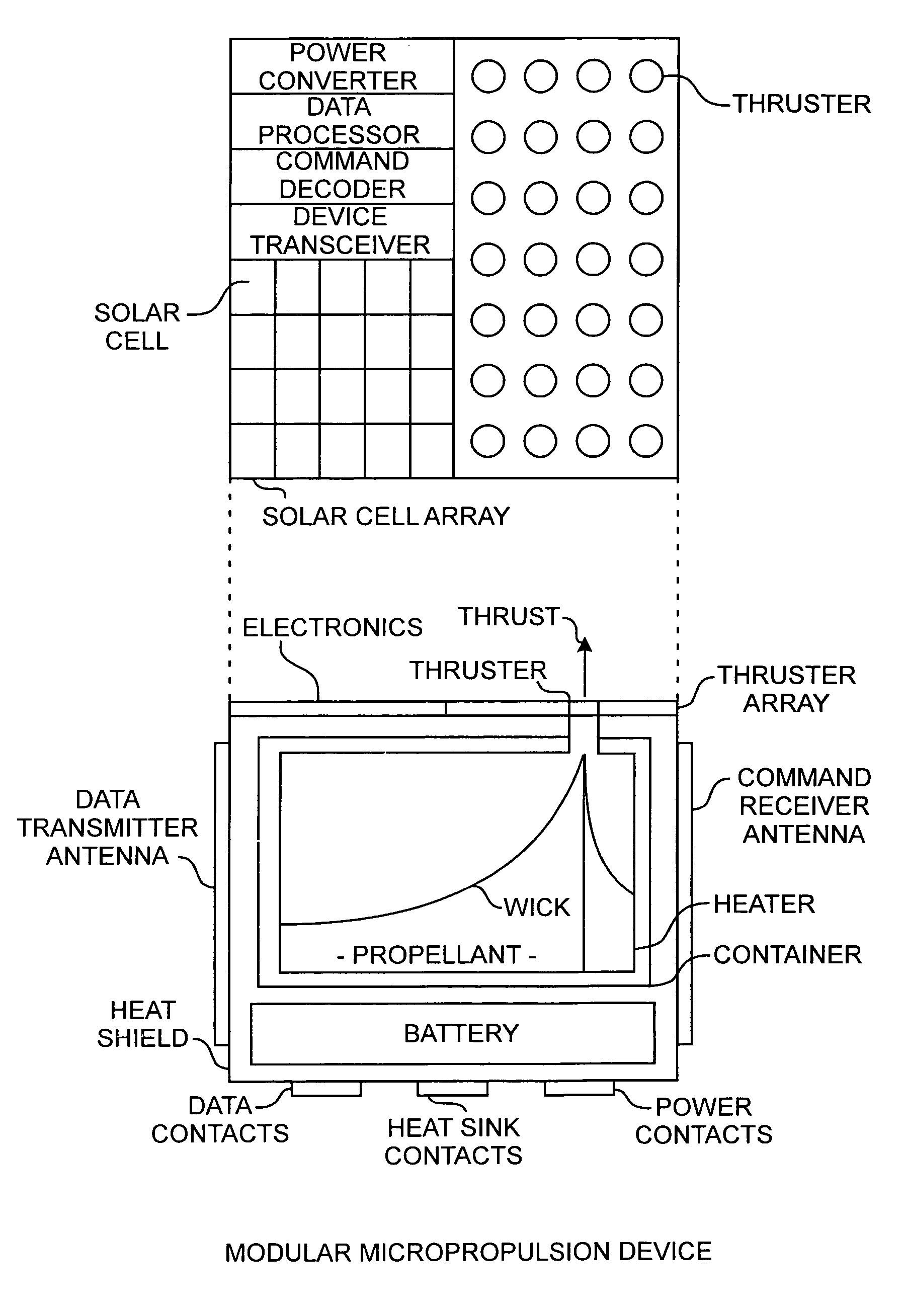
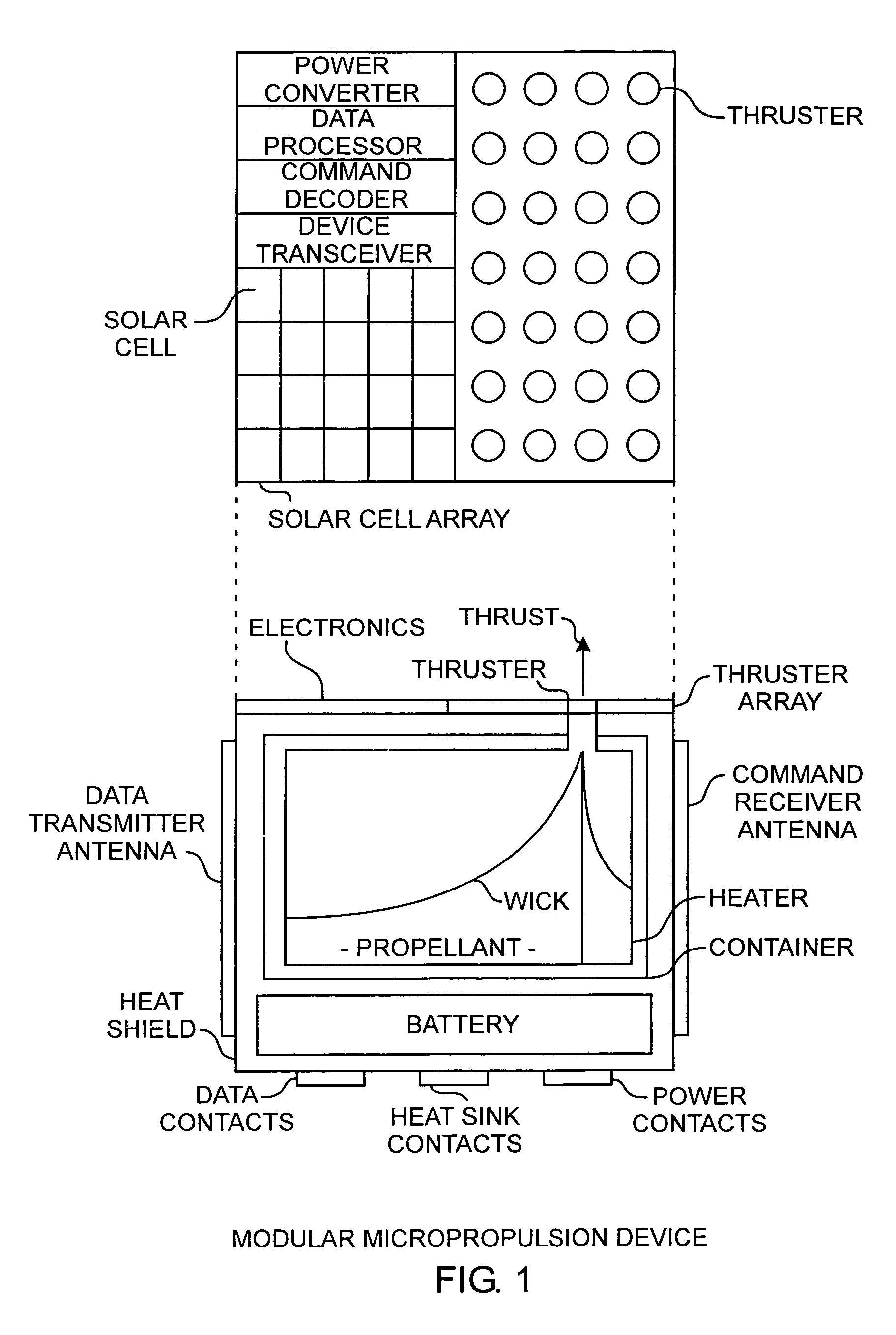
[0021]An embodiment of the invention is described with reference to the figures using reference designations as shown in the figures. Referring to FIG. 1, a modular micropropulsion device is preferably fashioned in the shape of a cube having on a top surface of electronics comprising a power converter, a data processor, a command decoder, a device transceiver, and a solar cell array. An exemplar solar cell in the solar cell array is designated as such. Also disposed on the top of the cube device is a thruster array for providing thrust. An exemplar thruster in the thruster array is designated as such. On opposing sides of the cube device are disposed a data transmitter antenna and a command receiver antenna. On the bottom of the cube are disposed data contacts, power contacts, and heat sink contacts. The cube is protected by a heat shield about the periphery of the cube. A battery is internally disposed in the cube device, preferably near the bottom of the cube device. Above the bat...


PUM


Abstract

A modular propulsion system includes an array of micromachined field effect electrostatic propulsion devices, each of which is an assembled micromachined device including an array of field effect electrostatic propulsion thrusters, a fuel container of propellant using passive plumbing, electronic power and command controls, with the array of devices disposed about and on a surface of a spacecraft for providing diverse propulsion needs.

Description

STATEMENT OF GOVERNMENT INTEREST[0001]The invention was made with Government support under contract No. FA8802-00-C-0001 by the Department of the Air Force. The Government has certain rights in the invention.FIELD OF THE INVENTION[0002]The invention relates to the field of propulsion devices and systems. More particularly, the present invention relates to-modular micropropulsion devices and systems using micron-sized field effect electrostatic propulsion thrusters well suited for controlling spacecraft.BACKGROUND OF THE INVENTION[0003]Developmental space propulsion systems have used macro field effect electrostatic propulsion thrusters that have sub-millimeter to millimeter-sized gaps to create large ion accelerating fields with smaller applied voltages than is possible with conventional ion thrusters, which typically require many thousands of volts. The resulting macro thrusters have a large specific impulse and have a large thrust. However, macro field effect electrostatic propuls...

Claims


Application Information

Patent Timeline
Patent Type & Authority Patents(United States)
IPC IPC(8): F03H1/00H05H1/00
CPCF03H1/005
Inventor BEKEY, IVAN
Owner THE AEROSPACE CORPORATION
Why Eureka
Try Eureka