Light emitting sheet module

a technology of light-emitting sheets and modules, which is applied in the direction of moving contacts, lighting and heating apparatuses, instruments, etc., can solve the problems of increased power consumption, light leakage, and large size of sheet switches b>10/b>, and achieves a high level of brightness

Inactive Publication Date: 2010-04-06
CITIZEN ELECTRONICS CO LTD
View PDF5 Cites 33 Cited by
  • Summary
  • Abstract
  • Description
  • Claims
  • Application Information

AI Technical Summary

Benefits of technology

[0016]Also, another object of the present invention is to provide a light emitting sheet module capable of staying in close contact with key switches and of providing light emission of the key switches with a high level of brightness, when the light emitting sheet module is installed in a switch board.

Problems solved by technology

However, the above-mentioned conventional sheet switches face the following problems.
Consequently, the problem arises that power consumption is increased and the sheet switch 10 becomes large in size.
Accordingly, if such a clearance exists around the light guiding plate 15, there is a problem that light may leak from the clearance so that an insufficient amount of light passes through the key tops 17 and variations in brightness of the sheet switch occur.
In addition, because each of the above-mentioned sheet switches 10 and 11 including an illumination device comprising the light guiding plate and the LEDs corresponding to the key switches are integrated, it is not possible to utilize only the illumination device function.
Therefore, there is a problem that the sheet switches can not be adapted flexibly to various devices in which structures of the key switches, or switch board or the like have different structures.

Method used


Image

  • Light emitting sheet module
  • Light emitting sheet module
  • Light emitting sheet module

Examples


first embodiment

[0037]A light emitting sheet module according to the present invention is explained.

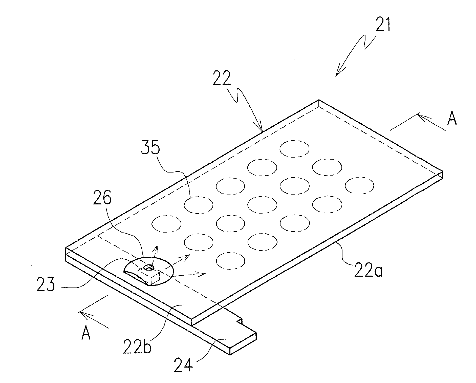
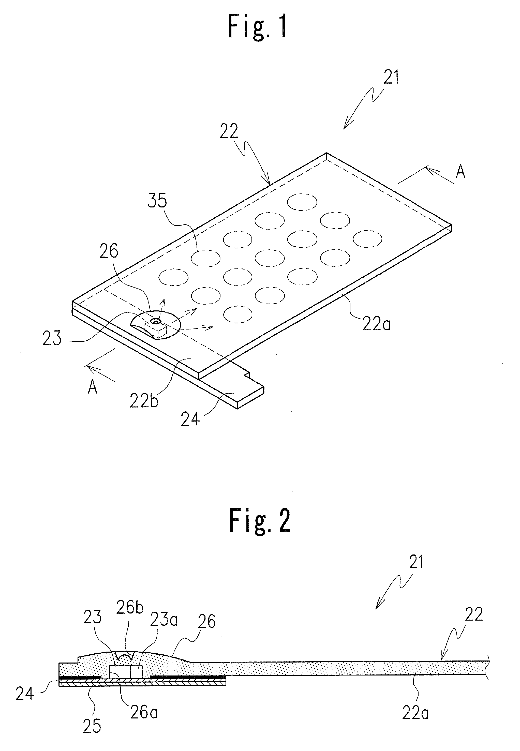
[0038]The light emitting sheet module according to the first embodiment of the present invention is shown in FIGS. 1 and 2. The light emitting sheet module 21 is a thin rectangular light guiding sheet 22 including an upper surface as an emission surface, a lower surface opposite the upper surface, and a circuit board 24 (hereinafter referred to as an LED board) on which is mounted at least one light emitting diode element or light emitting diode 23 (hereinafter referred to as an LED) which is a package including at least one light emitting diode element.

[0039]The LED 23 is disposed to be at one end portion of the light guiding sheet 22, in contact with a lower surface of the light guiding sheet. The LED board 24 has an elongate shape extending along a short side of the rectangular light guiding sheet 22.

[0040]The light guiding sheet 22 comprises a transparent or translucent thin sheet which is made o...

second embodiment

[0072]FIG. 6 illustrates a light emitting sheet module 51 according to the present invention.

[0073]The light emitting sheet module 51 in the second embodiment includes a light guiding sheet 52 having a light guiding part 52a and a plurality of LEDs 53 disposed on opposite sheet end portions 52b and 52c of the light guiding sheet 52, respectively. The light emitting sheet module is suitable in a case that the area of the light guiding part 52a is large or in a case that a high level of brightness needs to be obtained. The LEDs 53 are mounted on a pair of LED boards 54a and 54b, and each of the LED boards 54a and 54b disposed at each short side of the light guiding sheet, covered by the sheet end portions 52b and 52c of the light guiding sheet 52. A frame is may be formed by the pair of LED boards 54a, 54b and a connecting member 54c to connect the pair of LED boards so as to avoid the light guiding part 52a, namely the connecting member 54c is disposed outside of the light guiding pa...


PUM


Abstract

A light emitting sheet module includes a light guiding sheet to cover a plurality of key switches, at least one LED disposed on at least one end portion of the light guiding sheet, and a circuit board disposed on the one end portion of the light guiding sheet on which the LED is disposed. When the light emitting sheet module is, mounted on a switch board, it is capable of adaptation to key switches in a wide variety of forms and to illuminate the key switches with light emission of high brightness.

Description

CROSS-REFERENCE TO THE RELATED APPLICATIONS[0001]This application is based on and claims the priority benefit of each of Japanese Patent Application Nos. 2006-211545, filed on Aug. 3, 2006, and 2007-55535, filed on May 6, 2007, the disclosure of which is incorporated herein by reference in its entirety.BACKGROUND OF THE INVENTION[0002]1. Field of the Invention[0003]The present invention relates to a light emitting sheet module which is installed in an operation panel of each of various electronic instruments and has an illumination function.[0004]2. Description of Related Art[0005]A sheet switch 10 as shown in FIG. 13 is used as a key inputting part installed in each of various electronic instruments such as mobile phones, mobile information terminals or the like. The sheet switch 10 achieves its illumination function through provision of a plurality of light sources including light emitting diode elements 6, each of which is disposed about each of key switches 8.[0006]FIG. 14 illus...

Claims


Application Information

Patent Timeline
Patent Type & Authority Patents(United States)
IPC IPC(8): G01D11/28
CPCG02B6/0018G02B6/0021H01H13/83H01H2205/026H01H2227/016H01H2219/06H01H2219/062H01H2221/05H01H2227/002H01H2215/012Y10S362/80H04M1/22H01H13/704H01H13/00
Inventor MIYASHITA, ISAOAIHARA, KENSHI
Owner CITIZEN ELECTRONICS CO LTD
Why Eureka
Try Eureka