

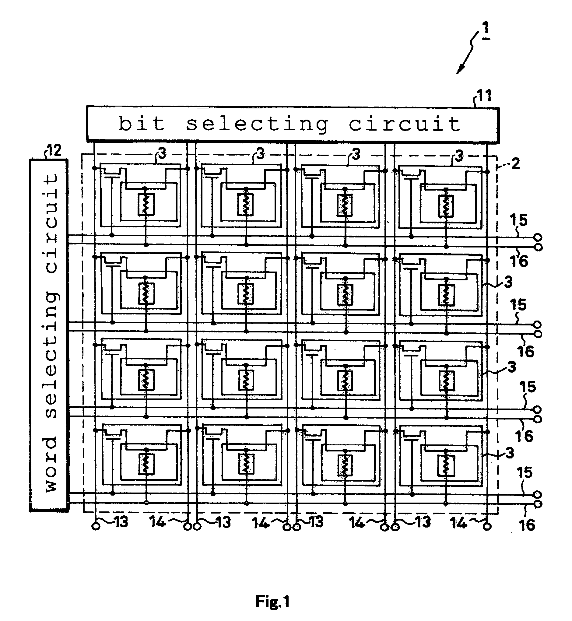
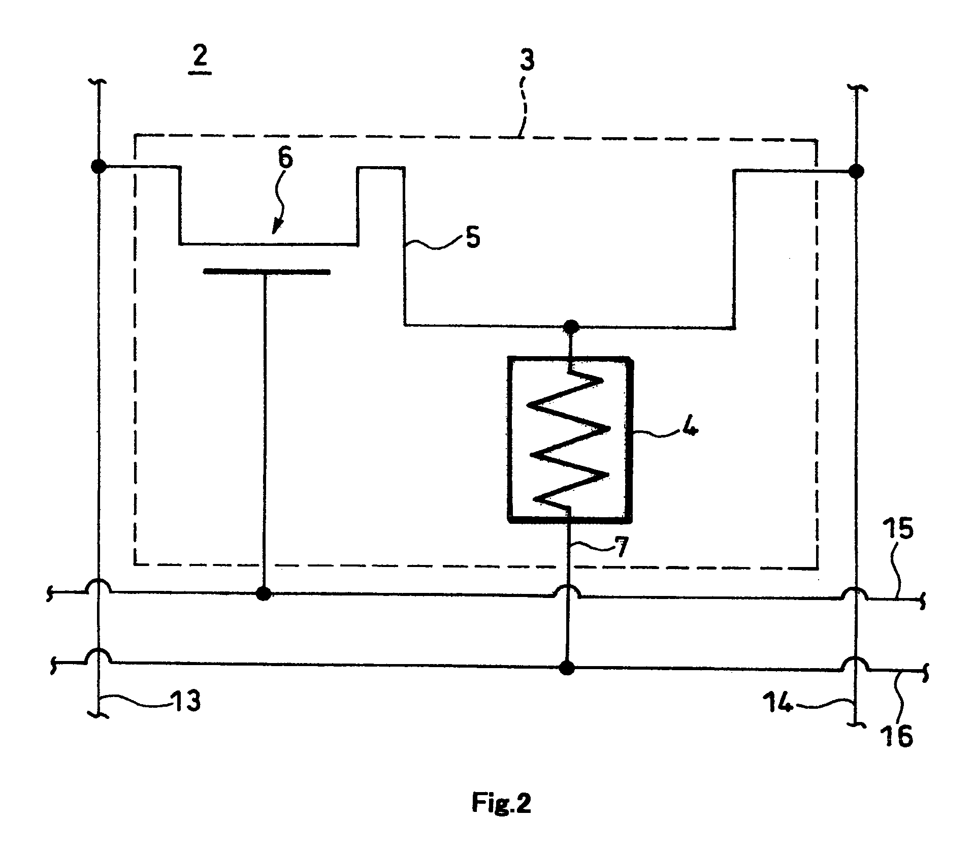
Magnetic memory including ferromagnetic yoke and antiferromagnetic layer
a magnetic memory and antiferromagnetic layer technology, applied in the field of magnetic memory, can solve the problems of insufficient power supply, anxiety about complicating the control of electric current and timing in the course of writing, and achieve the effects of stabilizing the state of magnetization, increasing the writing speed, and stabilizing the magnetic field
- Summary
- Abstract
- Description
- Claims
- Application Information
AI Technical Summary
Benefits of technology
Problems solved by technology
Method used
Image

Examples
example
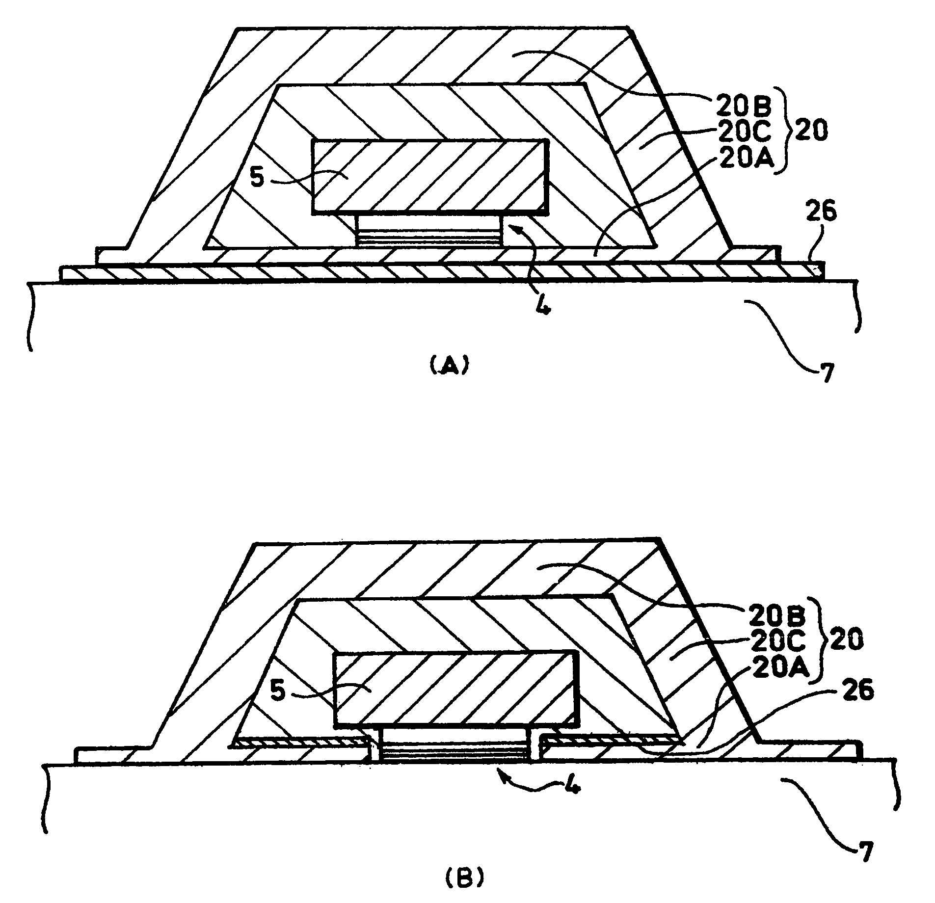
[0103]In a magnetic memory 201 of the third embodiment, four memory cells 203 (samples No. 1-4) were produced, a writing-grade wire 205A was supplied with an electric current, and a TMR element 204 was examined to determine the state of inversion consequently induced therein. Specifically, the size in the direction of length of the writing-grade wire 205A was set at 0.2 μm and the size in the direction of width thereof at 0.5 μm, the width of the writing-grade wire 205A at 0.5 μm, the size in the direction of length of the writing-grade wire 205A in the ferromagnetic yoke 220 at 0.2 μm, the wall thickness of the element side yoke 220A at 20 nm, and the wall thickness of the counterelement side yoke 220B at 50 nm. The state of inversion of the magnetic field of the TMR element 204 was determined by measuring the state of fluctuation of the MR ratio (%) of the TMR element 204. Incidentally, the MR ratio refers to the ratio expressed by the formula, {R (a . . . b)−R (a=b)} / R (a=b), whe...
PUM
 Abstract
Description
Claims
Application Information