Discharge lamp ballast, lighting system and projector

a technology of discharge lamp and discharge lamp, which is applied in the direction of electric variable regulation, process and machine control, instruments, etc., can solve the problems of erroneous operation of discharge lamp and peripheral circuit, and achieve the effect of reducing noise, high equipment reliability and reducing nois

Inactive Publication Date: 2010-04-06
MATSUSHITA ELECTRIC WORKS LTD
View PDF15 Cites 12 Cited by
  • Summary
  • Abstract
  • Description
  • Claims
  • Application Information

AI Technical Summary

Benefits of technology

[0006]It is therefore an object of the present invention to reduce noise from a starting means that applies starting voltage across a discharge lamp.
[0007]A discharge lamp ballast of the present invention comprises: a voltage step down converter connected to a DC power source with a positive terminal and a negative terminal; a converter control means that controls the converter; a first capacitor that applies DC voltage across a discharge lamp having a first end and a second end through DC power from the converter; and a starting means that applies starting voltage across the lamp in case of a starting mode. The converter is constructed with a diode, a first switching element and a first inductor. The diode has a cathode and an anode, and the anode is connected to the negative terminal of the DC power source and a negative voltage side of the first capacitor. The first switching element is connected between the cathode of the diode and the positive terminal of the DC power source. The first inductor is connected between the cathode of the diode and a positive voltage side of the first capacitor. In case of a steady operating mode after the starting mode, the converter control means turns the first switching element on and off at a high frequency so as to supply DC power for steady operating to the lamp via the first capacitor. For an aspect of the present invention, the starting means comprises a second inductor, a second capacitor, a second switching element, a third switching element and a starting control means. The second inductor is connected between the first end of the lamp and the positive voltage side of the first capacitor. The second capacitor is connected in parallel with the lamp and forms a resonance circuit together with the second inductor. The second switching element is connected between the positive terminal of the DC power source and the second end of the lamp. The third switching element is connected between the second end of the lamp and the negative voltage side of the first capacitor. The starting control means controls the second switching element and the third switching element. In case of the steady operating mode, the starting control means operates so as to include an on period of the third switching element while keeping the second switching element turned off. In case of the starting mode, the starting control means alternately turns the second switching element and the third switching element on and off so as to contribute resonance voltage of the resonance circuit for starting of the lamp. Thus, by contributing the resonance voltage for starting of the lamp, noise from the starting means can be reduced.
[0008]The present invention may comprise a transformer with a primary winding and a secondary winding, and utilize the primary winding as the second inductor. In this case, the secondary winding is connected in series with the lamp, while the series combination of the secondary winding and the lamp is connected in parallel with the secondary capacitor. Thus, induction voltage responding to a resonance current passing through the primary winding is superposed onto resonance voltage across the second capacitor, so that the starting voltage applied across the lamp is increased.
[0009]The second capacitor of the present invention may have capacitance smaller than that of the first capacitor. Thus, the second capacitor has capacitance smaller than that of the first capacitor and therefore the resonance current is reduced, while the first capacitor has capacitance larger than that of the second capacitor and therefore ripple voltage across the first capacitor for the lamp is reduced.
[0015]Therefore, the present invention achieves reduction of noise from the starting means and gives benefit of the noise reduction and high reliability in equipment such as a lighting system constructed with the ballast and the lamp, a projector constructed with the ballast and the lamp, or the like.

Problems solved by technology

However, when the above transformer provides the lamp with high voltage from several kV to 10 s kV, electromagnetic induction noise (flux) is radiated from the transformer and therefore there is a problem that the noise gives the ballast and peripheral circuits erroneous operation.

Method used


Image

  • Discharge lamp ballast, lighting system and projector
  • Discharge lamp ballast, lighting system and projector
  • Discharge lamp ballast, lighting system and projector

Examples


first embodiment

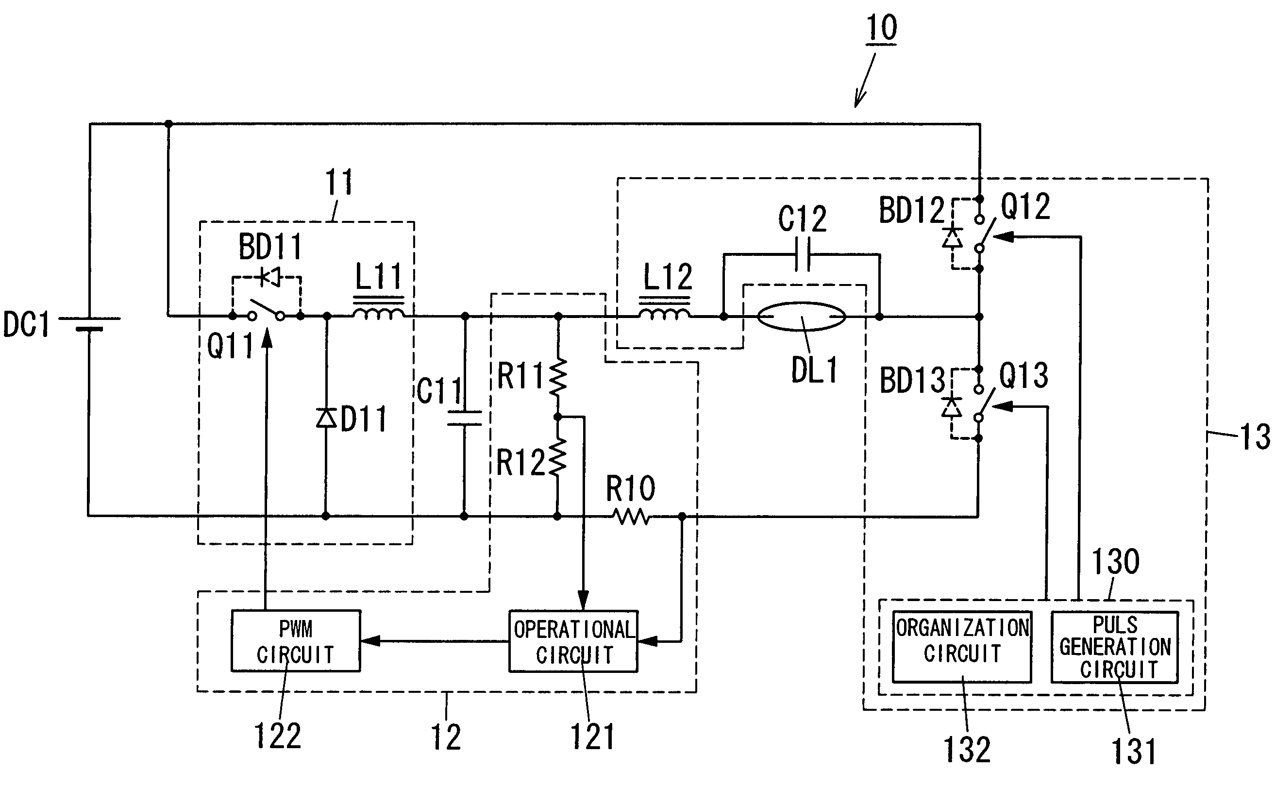
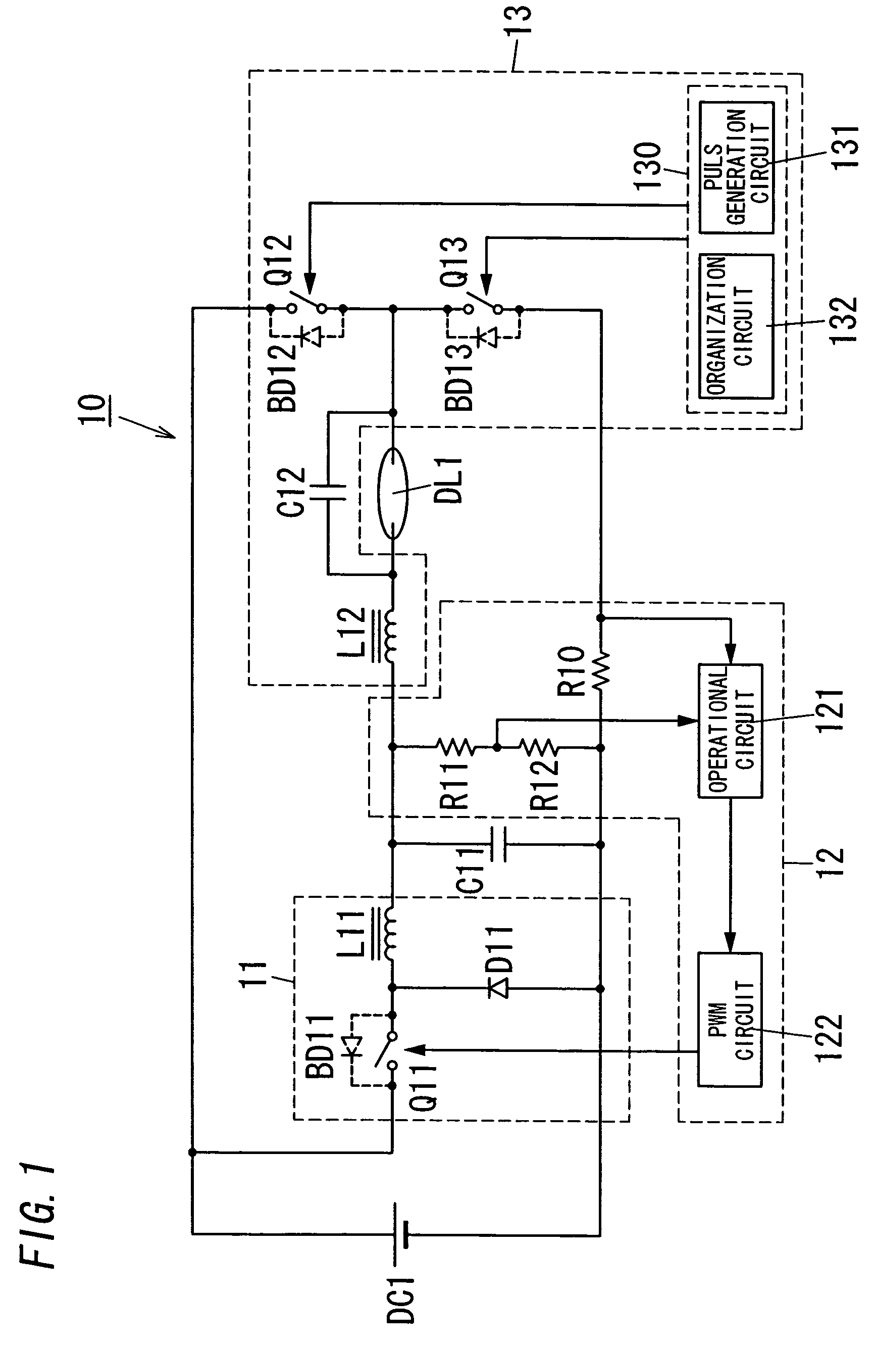
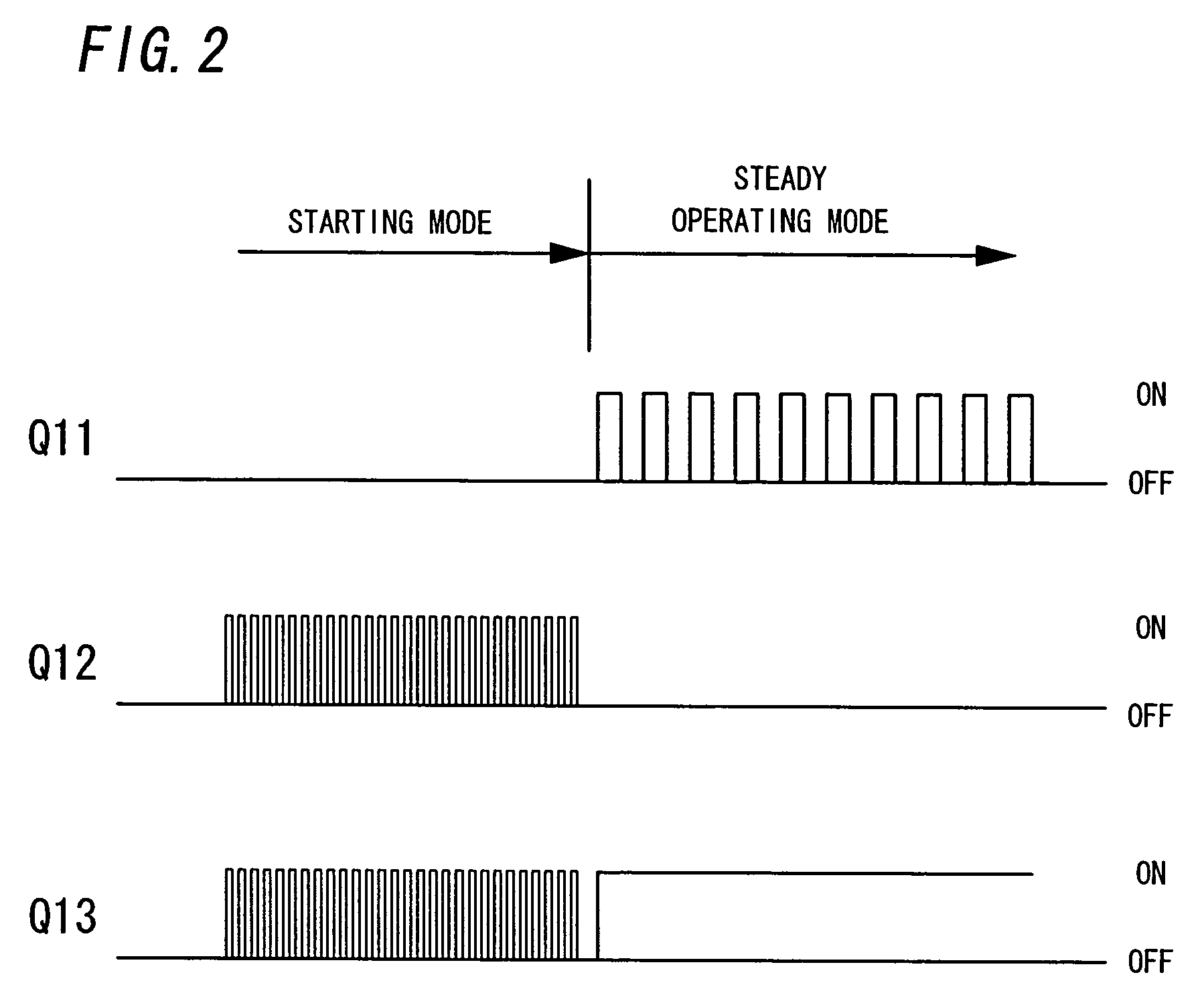
[0050]The starting controller 130 is constructed with a pulse generation circuit 131 and an organization circuit 132. In case of the starting mode, the pulse generation circuit 131 alternately turns the switching elements Q12 and Q13 on and off so that the lamp DL1 is started by resonance voltage of the above resonance circuit. In case of the starting mode, the circuit 131 in the first embodiment alternately turns the switching elements Q12 and Q13 on and off approximately at a resonance frequency (e.g., 115 KHz) of the resonance circuit in order to secure the starting voltage of the lamp DL1 through the resonance voltage.

[0051]In case of the steady operating mode, the organization circuit 132 operates so as to include an on period of the switching element Q13 while keeping the switching element Q12 turned off. In the first embodiment, the circuit 132 turns the switching element Q13 on and then holds the turn on, while keeping the switching element Q12 turned off in case of the stea...

second embodiment

[0058]In this second embodiment, the inductor L12 of FIG. 1 is replaced by the primary winding n1. The secondary winding n2 is utilized to superpose induction voltage responding to a resonance current passing through the primary winding n1 onto resonance voltage across a capacitor C22. The winding n2 is connected in series with the lamp DL2, while the series combination of the winding n2 and the lamp DL2 is connected in parallel with the capacitor C22. In FIG. 3, the winding n2 is also directly connected in series with the winding n1. The level of the induction voltage can be adjusted with a turn ratio (n1:n2) of the transformer T.

[0059]According to the second embodiment of the present invention, since the induction voltage responding to the resonance current passing through the primary winding n1 is superposed onto the resonance voltage across the capacitor C22, staring voltage applied across the lamp DL2 can be increased.

[0060]FIG. 4 illustrates a discharge lamp ballast 30 for a d...

third embodiment

[0061]In the steady operating mode (FIG. 5), the intermittent organization circuit 332 in this third embodiment holds the switching element Q32 off and also turns the switching element Q33 on and off, while the circuit 332 synchronizes the turning on and off of the switching element Q33 with the turning on and off of the switching element Q31.

[0062]According to the third embodiment of the present invention, it is possible to reduce noise from the starter 33 that applies starting voltage across the lamp DL3 as well as the first embodiment. The intermittent organization circuit 332 of the third embodiment is also applicable to the starting controller 230 in the second embodiment.

[0063]FIG. 6 illustrates a discharge lamp ballast 40 for a discharge lamp DL4 (e.g., a DC discharge lamp such as a HID lamp or the like). This ballast 40 is characterized by a frequency sweep circuit 433 further provided in a starting controller 430 of a starter 43 as compared with the first embodiment that is...


PUM


Abstract

A discharge lamp ballast having a starting circuit including a second inductor connected between a first end of a discharge lamp and the positive voltage side of a first capacitor; a second capacitor forming a resonance circuit together with the second inductor; a second switching element connected between the positive terminal of a DC power source and the second end of the lamp; a third switching element connected between the second end of the lamp and the negative voltage side of the first capacitor; and a starting controller that controls both switching elements. The starting controller alternately turns both switching elements on and off so as to contribute resonance voltage of the resonance circuit for starting of the lamp in case of the starting mode.

Description

BACKGROUND OF THE INVENTION[0001]1 Field of the Invention[0002]The invention relates to discharge lamp ballasts, lighting systems and projectors that apply starting voltage across discharge lamps at a starting mode and supply the lamps with DC power for steady operating (lighting) at a steady operating mode after the starting mode.[0003]2 Description of the Related Art[0004]A discharge lamp ballast for a DC discharge lamp comprises a voltage step down converter in order to supply the lamp with DC power for a steady operating state at a steady operating mode. Also, in case that the lamp is a high pressure discharge lamp (HID lamp) such as a metal halide lamp or the like, the ballast is provided with an igniter that generates high voltage pulse from several kV to 10 s kV with a pulse transformer (see, e.g., Japanese Patent Publication number H10-144488).[0005]However, when the above transformer provides the lamp with high voltage from several kV to 10 s kV, electromagnetic induction n...

Claims


Application Information

Patent Timeline
Patent Type & Authority Patents(United States)
IPC IPC(8): H05B41/36H05B41/288
CPCH05B41/2883
Inventor NAKADA, KATSUYOSHIKONISHI, HIROFUMIHASEGAWA, JUNICHIWATANABE, KOJIUCHIHASHI, KIYOAKISASAKI, TOSHIAKI
Owner MATSUSHITA ELECTRIC WORKS LTD
Why Eureka
Try Eureka