Semiconductor memory device

a memory device and semiconductor technology, applied in the field of semiconductor memory devices, can solve the problems of increasing transistor size and not considering the rise speed of the word line, and achieve the effects of reducing the drivability of the access transistor in the memory cell, and improving the snm at the time of reading

Inactive Publication Date: 2010-04-06
RENESAS ELECTRONICS CORP
View PDF8 Cites 15 Cited by
  • Summary
  • Abstract
  • Description
  • Claims
  • Application Information

AI Technical Summary

Benefits of technology

[0009]In the configuration shown in the patent document 1, a memory cell transistor takes the form of a thin film transistor (hereinbelow, called TFT). Even in the case where the threshold voltage of the TFT varies, by changing the voltage amplitude of a selected word line by the level shifter, the margin at the time of reading is improved. Concretely, in the patent document 1, at the time of reading data, a selected word line is driven at a voltage level lower than that of the power supply voltage of a memory cell. The gate voltage of an access transistor in the memory cell decreases, the current drivability drops and, as a result, a static noise margin (hereinbelow, abbreviated as SNM) is assured and data destruction at the time of reading data can be prevented.
[0012]Therefore, an object of the present invention is to provide a semiconductor memory device realizing higher rising speed of a word line while assuring a read margin.
[0016]In the semiconductor memory device of the embodiment, after rising of the word line, the voltage of the power supply node of the word line driver is set to be lower than the power supply voltage of the memory cell. Therefore, the voltage of a selected word line at the time of reading can be made low, the drivability of the access transistor in the memory cell is decreased, and the SNM at the time of reading is improved, that is, data destruction at the time of reading data can be prevented.
[0017]At the time of rising of a word line, the voltage of the power supply node of the word line driver is set to the same level as that of the power supply voltage of the memory cell. Therefore, the rising speed of the word line can be maintained high.
[0018]Further, by providing a first voltage supply circuit including a transistor element for precharging the voltage of the power supply node of the word line driver to the power supply voltage level of the memory cell in addition to the second voltage supply circuit, the area of transistor elements constructing the voltage supply circuit can be decreased. As a result, the area of the whole voltage supply circuit can be reduced.

Problems solved by technology

However, the voltage level is fixed when the word line is driven, and rising speed of the word line is not considered.
However, in the case of increasing such current driving force, the transistor size increases, the occupation area of the word line driver or a circuit for generating a word line voltage enlarges.

Method used


Image

  • Semiconductor memory device
  • Semiconductor memory device
  • Semiconductor memory device

Examples


first embodiment

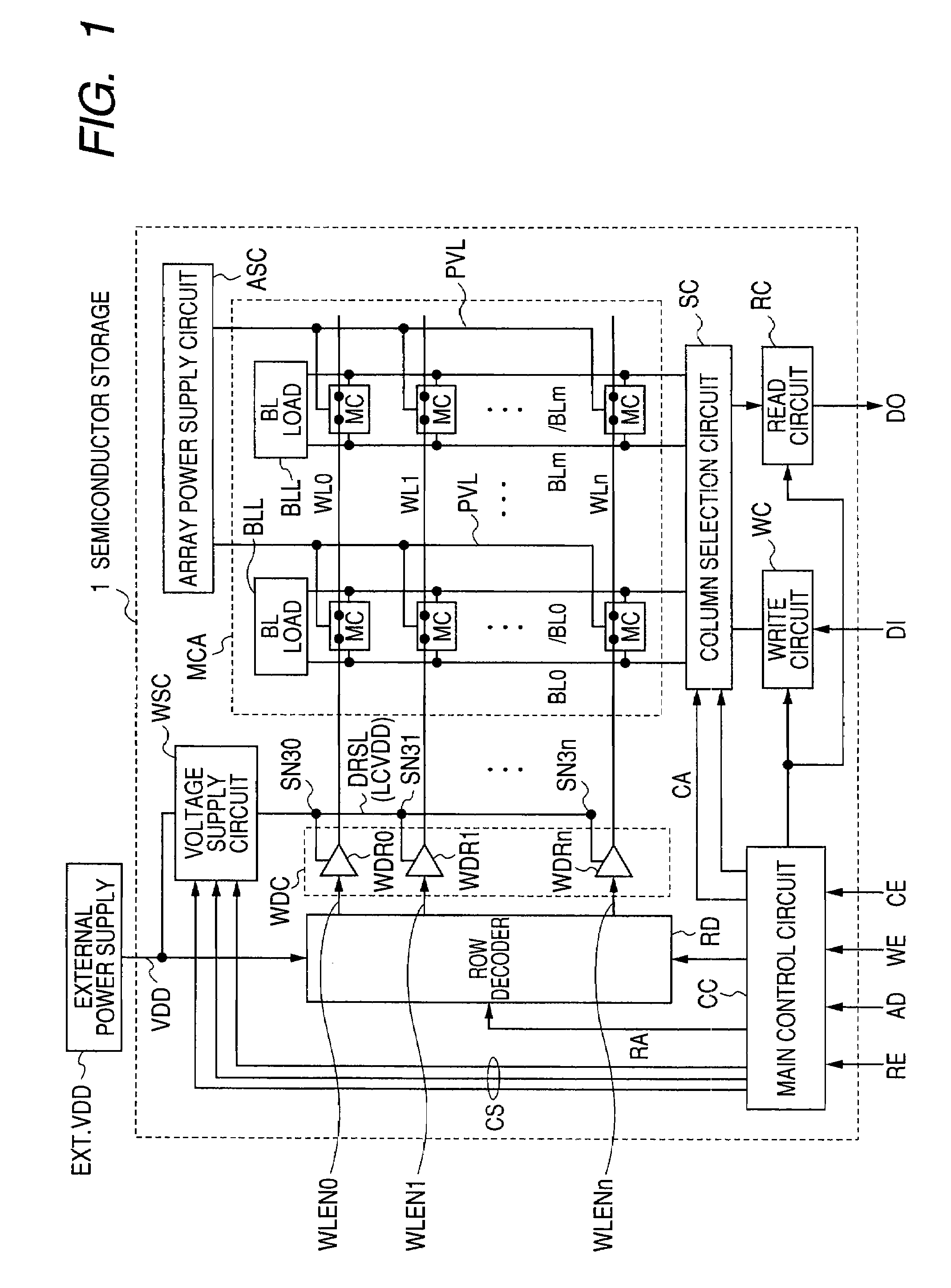
[0033]FIG. 1 is a diagram schematically showing a general configuration of a semiconductor memory device 1 as a first embodiment. In FIG. 1, the semiconductor memory device 1 includes a memory cell array MCA in which memory cells MC are arranged in a matrix. In FIG. 1, as an example, the memory cells MC are arranged in “n” rows and “m” columns in the memory cell array MCA.

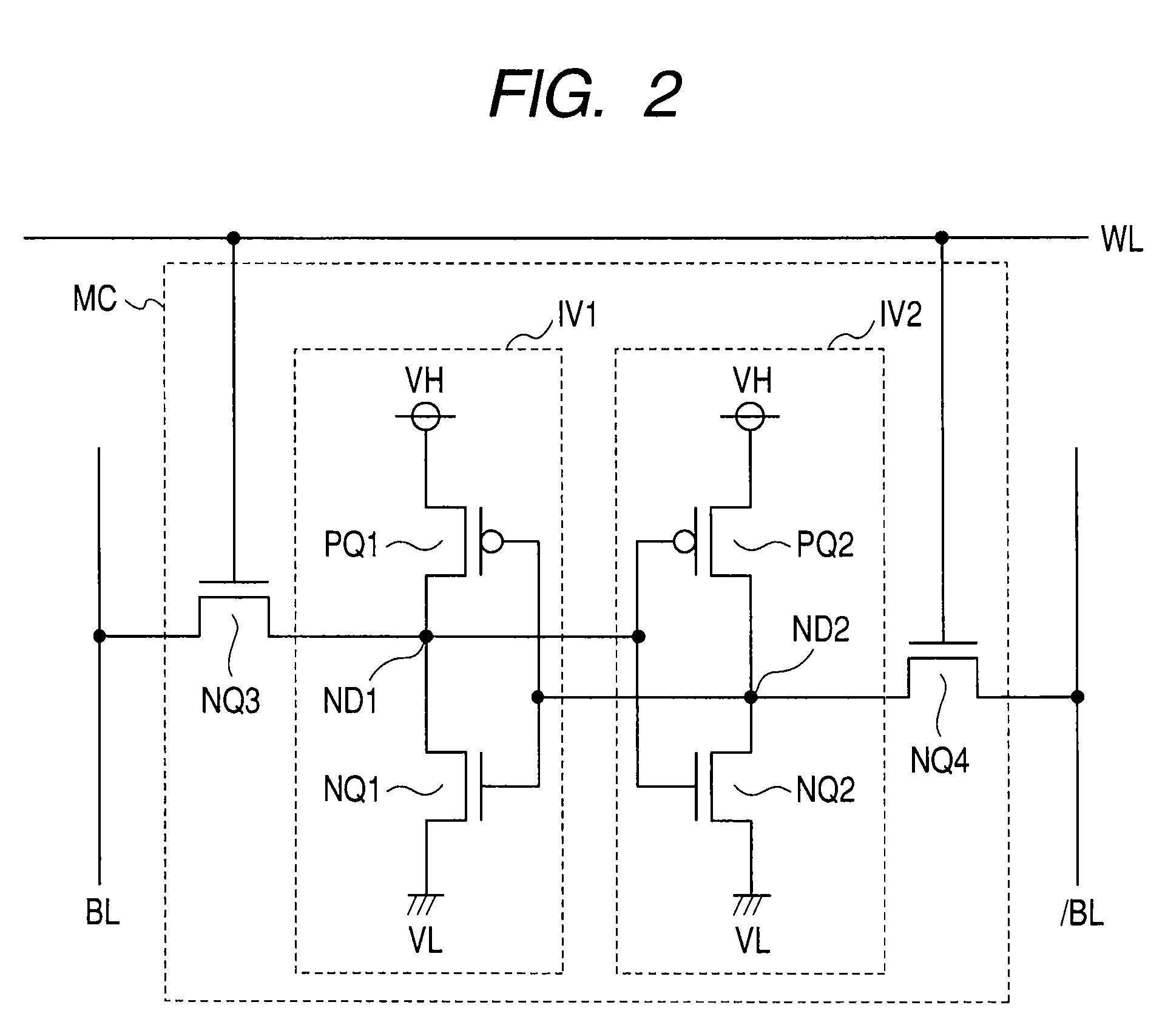
[0034]Word lines WL0 to WLn are arranged in correspondence with the rows of the memory cells MC, and the memory cells MC are connected to word lines WL of the corresponding rows. Bit line pairs BL0 and / BL0 to BLm and / BLm are disposed in correspondence with the columns of the memory cells MC. The memory cell MC is a static memory cell and complementary data is transmitted to the complementary bit line pairs BL0 and / BL0 to BLm and / BLm.

[0035]In correspondence with each of the pairs of bit lines BL and / BL, a bit line load (BL load) BLL is provided. At the time of reading memory cell data, the bit line load BLL pul...

second embodiment

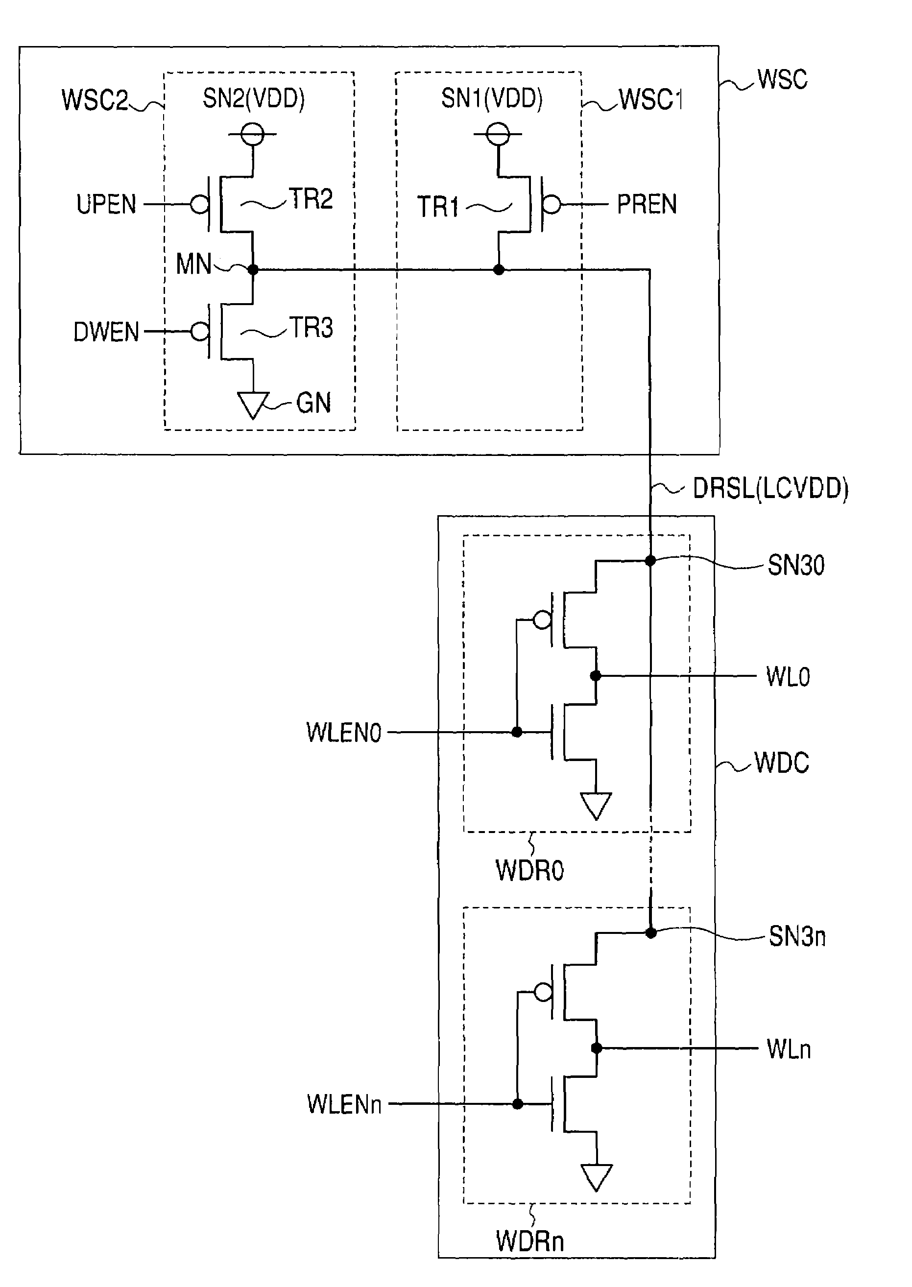
[0097]FIG. 10 is a diagram schematically showing a voltage supply circuit WSC and its periphery as a second embodiment of the invention. The configuration of the voltage supply circuit WSC shown in FIG. 10 is different from that of the voltage supply circuit WSC shown in FIG. 3 with respect to the point that a MOS capacitor MCAP is disposed in the source line DRSL of the word line driver (driver power supply line). The other configuration of the circuit shown in FIG. 10 is the same as that of FIG. 3. The same reference numerals are designated to corresponding parts and their detailed description will not be repeated.

[0098]In the first embodiment, the wiring capacity of the source line DRSL of the word line driver (driver power supply line) is used. By using a voltage accumulated in the wiring capacity, the speed of rising of the word line WL is increased. That is, when the wiring capacity of the source line DRSL of the word line driver (driver power supply line) is large, the speed ...

third embodiment

[0101]FIG. 11 is a diagram showing a voltage supply circuit WSC and its periphery according to a third embodiment of the invention. The configuration of the voltage supply circuit WSC shown in FIG. 11 is different from that of the voltage supply circuit WSC shown in FIG. 3 with respect to the point that a wire WI extends in the word line WL direction in addition to the normal wire of the word line driver source line DRSL (driver power supply line). The parasitic capacitance of the wire WI is used as capacitance of holding the precharge voltage of the driver power supply line DRSL.

[0102]The other configuration of the circuit shown in FIG. 11 is the same as that of FIG. 3. The same reference numerals are designated to corresponding parts and their detailed description will not be repeated.

[0103]FIG. 12 shows an example of the configuration of a semiconductor chip CH of a system LSI (Large Scale Integration). In FIG. 12, on the semiconductor chip CH, a number of functions such as a log...


PUM


Abstract

This invention discloses a semiconductor memory device having a voltage supply circuit for generating a driver power supply voltage. The voltage supply circuit is provided with a first voltage supply circuit for precharging the driver power supply voltage to a power supply voltage level of a memory cell, and a second voltage supply circuit for supplying a voltage lower than the power supply voltage level of the memory cell as the driver power supply voltage.

Description

CROSS-REFERENCE TO RELATED APPLICATIONS[0001]The disclosure of Japanese Patent Application No. 2007-45401 filed on Feb. 26, 2007 including the specification, drawings and abstract is incorporated herein by reference in its entirety.BACKGROUND OF THE INVENTION[0002]The present invention relates to a semiconductor memory device and, more particularly, to a configuration of a static semiconductor memory device capable of stably reading data.[0003]The term “MOS” originally stands for Metal-Oxide-Semiconductor as a stack structure. However, particularly in a field effect transistor having a MOS structure (hereinbelow, simply called “MOS transistor”), materials of a gate insulating film and a gate electrode are improved from the viewpoint of improvement in integration and manufacturing process in recent years.[0004]For example, in a MOS transistor, from the viewpoint of, mainly, forming a source and a drain in a self-aligning manner, polysilicon is employed in place of a metal as the mate...

Claims


Application Information

Patent Timeline
Patent Type & Authority Patents(United States)
IPC IPC(8): G11C8/00
CPCG11C11/412G11C5/147G11C11/413G11C8/08
Inventor TSUKUDE, MASAKI
Owner RENESAS ELECTRONICS CORP
Why Eureka
Try Eureka