
WLAN handover for a mobile terminal moving from a first to a second network

a mobile terminal and network switch technology, applied in the direction of data switching by path configuration, wireless commuication services, electrical devices, etc., can solve the problems of low handover, difficult to decide which access point to use, and unsolved problems, and achieve efficient wlan handover

Active Publication Date: 2010-04-06
INTERDIGITAL CE PATENT HLDG
View PDF32 Cites 80 Cited by
  • Summary
  • Abstract
  • Description
  • Claims
  • Application Information

AI Technical Summary

Benefits of technology

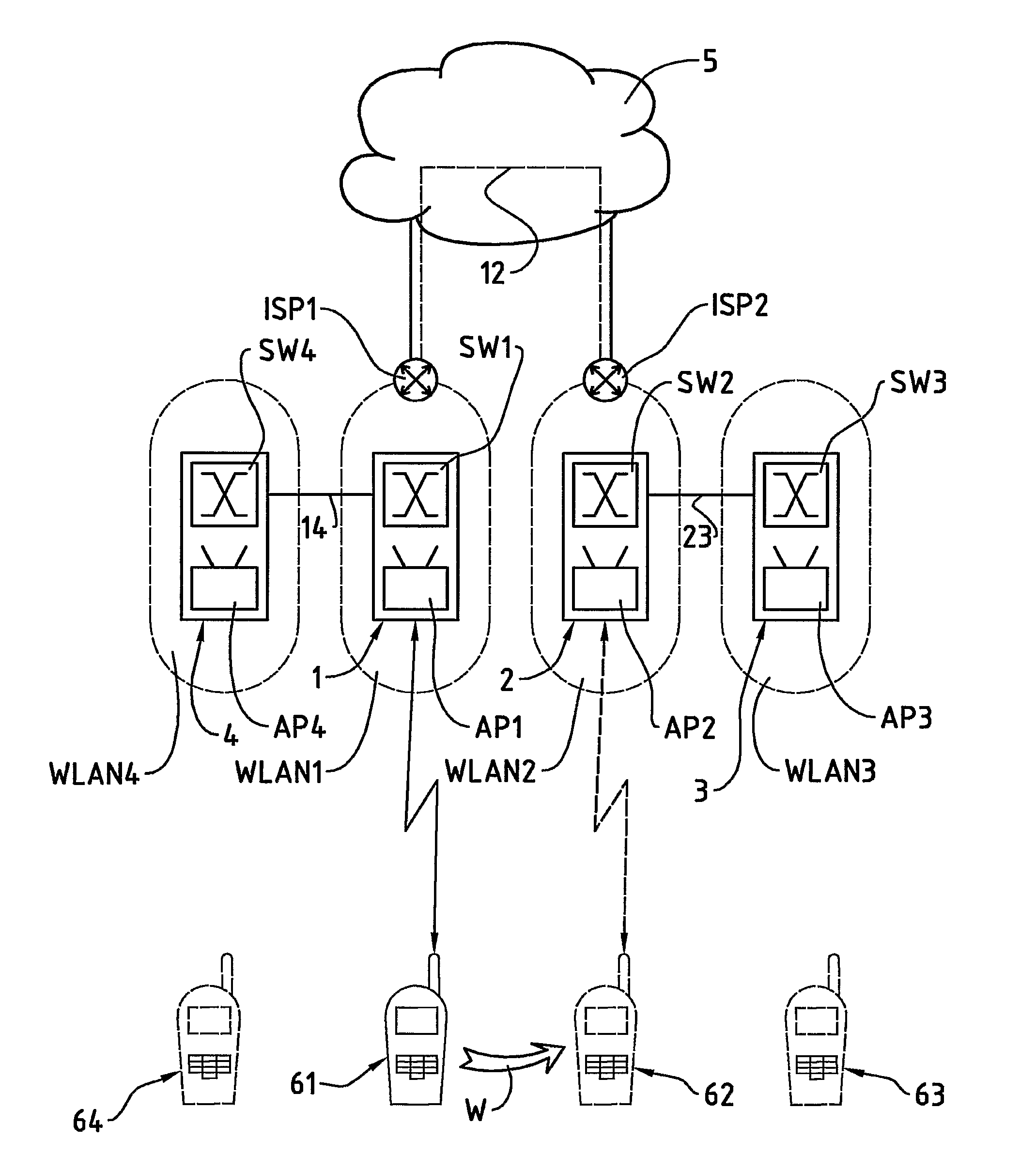
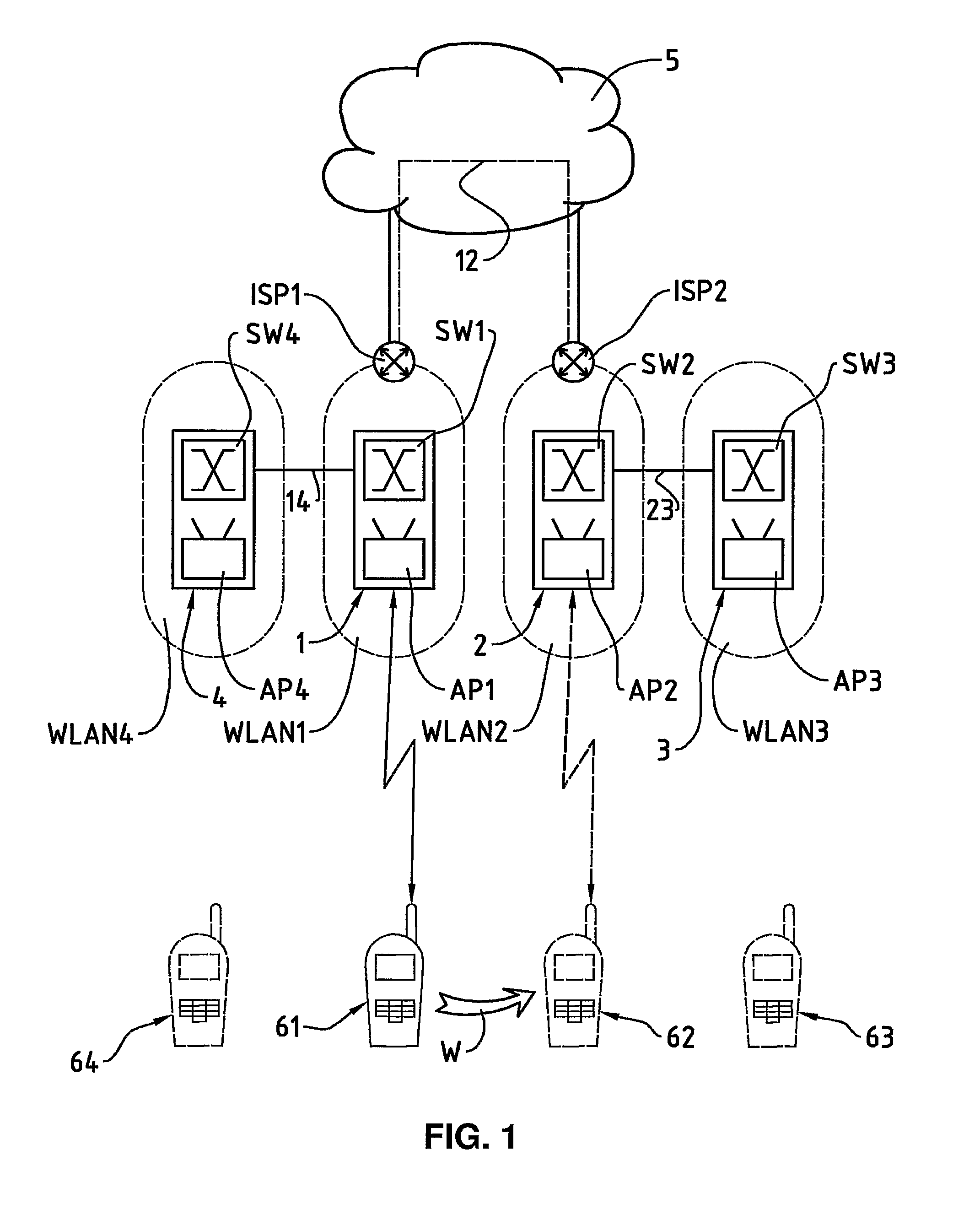
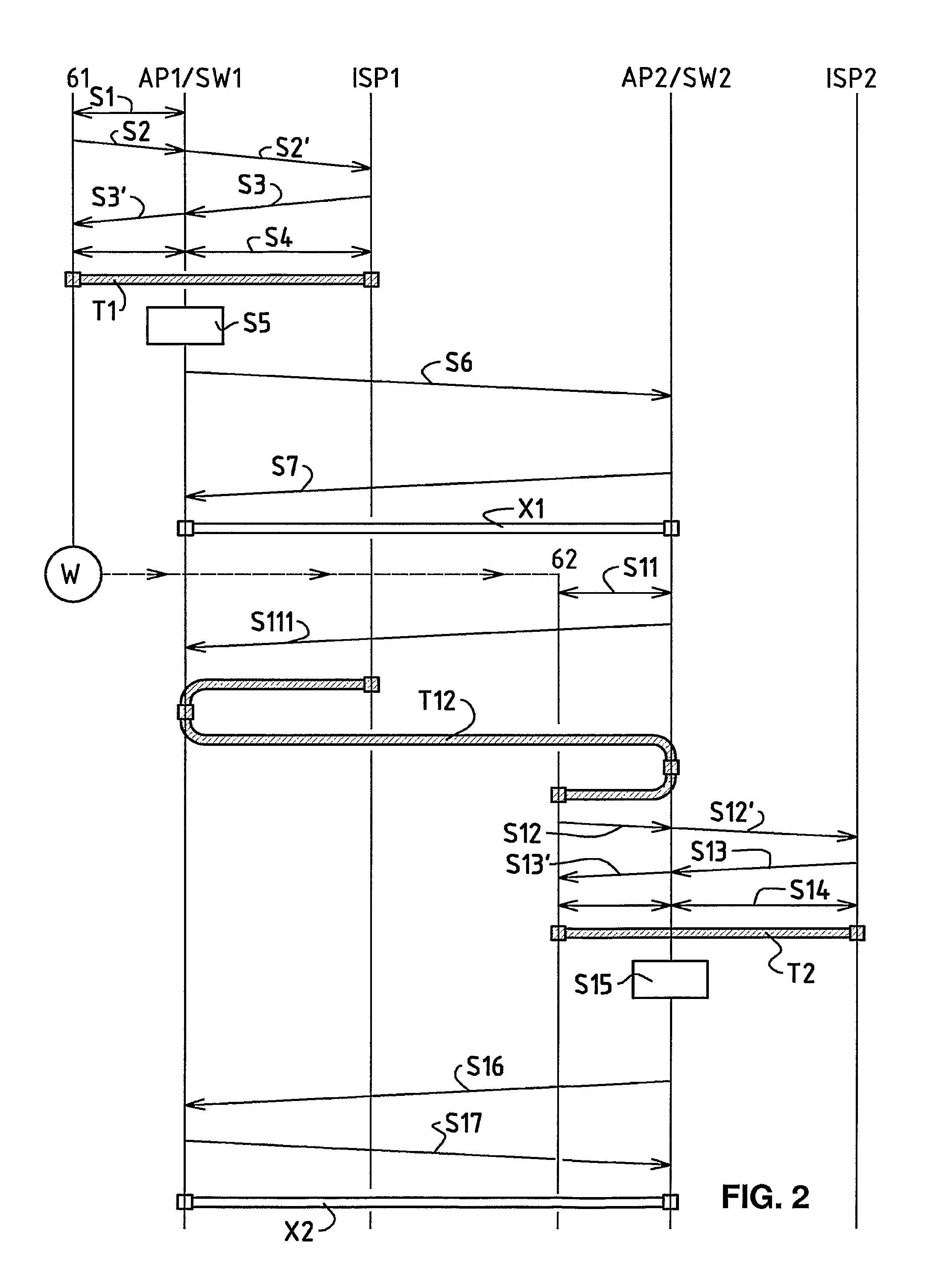
[0010]The above-mentioned objects are achieved through the present invention in that the mobile communication terminal is registered in a first Internet switching unit via a first access point unit of a first wireless local network and via a first local network switching unit (SW1) connected to the first access point unit, in that a first Internet address is transmitted from the first Internet switching unit to the mobile communication terminal, in that a first access for the mobile communication terminal to the Internet network is provided, using the first Internet address, whereas the first access is via the first access point unit, via the first local network switching unit, and via the first Internet switching unit, in that in the first local network switching unit a device-specific address of the mobile communication terminal is registered, in that the registered device-specific address and a network identification for the first wireless local network is transmitted from the first local network switching unit to a plurality of bordering further local network switching units, and in that the plurality of bordering further local network switching units are configured for providing a plurality of further accesses for the mobile communication terminal at a moved location to the Internet network using the first Internet address, whereas the plurality of further accesses is via a plurality of further access point units and corresponding further bordering local network switching units, via the first local network switching unit and via the first Internet switching unit. Such wireless local networks and such a mobile communication terminal have the advantage that access to an Internet network for a mobile communication terminal can be achieved with an efficient WLAN handover also for spread-out wireless networks. Since a device-specific address for the mobile communication terminal is registered in the first local network switching unit, and this registered address is transmitted together with a network identification for the first wireless local network to bordering further local network switching units, sufficient information exists—with the network identification and the device-specific address—at the point in time of movement of the mobile communication terminal to a new location of a bordering second access point unit, at the second local network switching unit, assigned to this second access point unit, such that data may be instantly exchanged between the mobile communication terminal, the second local network switching unit, the first local network switching unit and an Internet network. Through this method, a robust and efficient WLAN handover is achieved. Moreover, deployment of local network switching units can be easily performed.
[0017]In a further embodiment variant, the access point unit, the local network switching unit and / or the Internet switching unit is checked by the mobile communication terminal via security keys, via policies and / or via one or more authentication methods. This embodiment variant has the advantage, among other things, that the mobile communication terminal can identify network elements and can establish access to an Internet network e.g. only with respect to certain providers.

Problems solved by technology

An efficient WLAN handover between, for example, wireless local networks spread out over larger geographic regions or between different network providers, is, on the other hand, an unsolved problem.
When a mobile terminal is just on the border of the ranges of two different access points, it may become difficult to decide which of these access points shall be used.
If efficiency of a WLAN handover is low, also robustness for connecting to a WLAN in such a situation as is low.
Robustness may be even more degraded due to the fact that some central server behind the access points has to manage connections from the mobile terminal to the Internet.
However, when a mobile terminal switches its registration between different access points back and forth, the design of a robust central server for managing connections from the mobile terminal to the Internet becomes a difficult task.
A further disadvantage in the state of the art is handling of a WLAN handover between different network providers.
Even if different network providers would like to share access points in between each other, such that customers of a first network provider may benefit from network resources of a second network provider, such a sharing of access points is not possible in the state of the art.
With mobile IP it is not possible, however, to achieve a sufficiently efficient WLAN handover.
With mobile IP it is also not possible to provide a robust WLAN handover.
And finally, with mobile IP it is also not possible that network providers may share network resources in between each other.
Schulzrinne et al. consider SIP-based mobility to be less suitable for TCP-based applications.
With SIP based handover, however, it is not possible to provide for a sufficiently efficient WLAN handover.
It is as well not possible to provide for a robust WLAN handover.
And finally, with SIP based handover it is also not possible that network providers may share network resources in between each other.
A disadvantage of the method according to US 2003 / 0185172 is that a sufficiently efficient WLAN handover is difficult to achieve.
It is also a disadvantage that robustness of a WLAN handover cannot be achieved.
When the mobile node moves from a first network provider to a second network provider, it is a disadvantage that the mobile node has to be newly registered to the second network provider.

Method used


Image

  • WLAN handover for a mobile terminal moving from a first to a second network
  • WLAN handover for a mobile terminal moving from a first to a second network
  • WLAN handover for a mobile terminal moving from a first to a second network

Examples


Embodiment Construction

[0023]In FIG. 1, the reference numeral 61 refers to a wireless communication terminal, for example a laptop or palmtop computer, for instance a so-called Personal Digital Assistant (PDA), or a mobile telephone. The wireless communication terminal 61 comprises a communication module for data communication via a wireless local network, a so-called WLAN (Wireless Local Area Network). The wireless local network is preferably based on radio waves, for example according to the standard IEEE 802.11 (Institute of Electrical and Electronics Engineers) or according to a standard for a piconet, e.g. according to the standard known by the name Bluetooth. It can also be based on infrared, however. Subsequently, the terms mobile communication terminal 61 and moved mobile communication terminal 62, 63, 64 are used, whereas the mobile communication terminal 61 is initially located at a first location and whereas, through a movement W from the first to the second location, the moved mobile communica...


PUM


Abstract

A method, a system, and a local network switching device for providing access for a mobile communication terminal and the mobile communication terminal at a moved location to an Internet network via wireless local networks. The mobile communication terminal is moved from a first network to a second network. The WLAN handover, necessary therefore, takes place efficiently and in a robust manner, by providing access for the mobile communication terminal in the first network, by transmitting a device-specific address to a plurality of bordering networks, and by configuring further accesses on the plurality of bordering networks. After moving the mobile communication terminal, access to an Internet network can be continued immediately via the second network, via the local network switching unit of the second network, and via the local network switching unit of the first network.

Description

BACKGROUND OF THE INVENTION[0001](1) Field of the Invention[0002]The present invention relates to a method, a system and a local network switching unit for providing access for a mobile communication terminal and the moved mobile communication terminal to an Internet network via wireless local networks. The invention relates in particular to a method and system for the efficient handover of the access to an Internet network to a mobile communication terminal which is moved from a first wireless local network to a further wireless local network.[0003](2) Description of the Related Art[0004]Wireless local networks, so-called Wireless Local Area Networks (WLAN), serve as communication systems for communicating with other communication units for users with mobile communication terminals. Wireless local networks are used primarily as access networks for access to a fixed network, and in particular for access to the Internet. In a WLAN, data are transmitted in each case via an air interfa...

Claims


Application Information

Patent Timeline
IPC IPC(8): H04W4/00H04W36/00H04L12/28H04W36/14H04W36/30
CPCH04W36/0016H04W36/30H04W36/02H04W36/304
Inventor DE FROMENT, ERIC
Owner INTERDIGITAL CE PATENT HLDG
Learn More