Panel edge joint

a panel and edge joint technology, applied in the direction of vehicle/pulley ropes, building components, refrigeration devices, etc., can solve the problems of reducing the efficiency of the refrigeration unit, affecting the efficiency of the system, and heat loss being the major source of reducing efficiency, so as to achieve a deeper and tighter fit

Inactive Publication Date: 2010-04-13
LUCAS JAMES WALTER +1
View PDF16 Cites 4 Cited by
  • Summary
  • Abstract
  • Description
  • Claims
  • Application Information

AI Technical Summary

Benefits of technology

[0020]Additionally, by providing extraneous length and width in the deformable sleeve, the fit ensures the male part is wedged in the female part so that it is difficult to prise the two mated panels apart. This provides extra strength to the panels, increasing the joint strength and the wind loading of the joined panels.
[0022]Further preferably, the deformable sleeve may include a third bead to stop the flow of water to the panel joint, thereby reducing the risk of water build up or corrosion of the panel joint. The bead may be formed as a flange along one side of the deformable sleeve in a unilateral direction to deflect the flow of liquid away from the joint.
[0023]The deformable sleeve is generally made of a suitable material to withstand the temperature gradient between the cool room and the outside air. Preferably the deformable sleeve is formed from a thermoplastic elastomer which has rubber-like characteristics as well as properties allowing it to be processed and recycled like thermoplastic materials. Santoprene™ (Advanced Elastomeric System) is an example of such a compound of rubber and plastic, suitable to withstand cool room temperatures. While Santoprene has functional performance and properties similar to conventional thermoset rubber products, it may be processed with the speed, efficiency, and economy of thermoplastics. Additionally, Santoprene is easier to recycle as scrap and provides closer dimensional consistency and product quality compared to thermoset rubber products, as Santoprene has a small amount of permanent plastic deformation and little shrinkage. Additionally, Santoprene is well suited for temperatures below 0° C. as its brittle point (for most grades) allow flexibility to −57° C. These thermal properties allow Santoprene to withstand the low temperatures of the cool room and temperature differential between inside and outside temperatures without becoming brittle or rigid.
[0029]Preferably a third bead may be provided between the deformable sleeve and the female part to ensure that no water or liquid is allowed to flow therebetween. The bead may be formed as a flange, located in a unilateral direction away from the edge of the deformable sleeve. The direction of the flange ensures that the seal becomes stronger as liquid, in particular water, pushes against the deformable sleeve.

Problems solved by technology

These heat losses and gains affect the efficiency of the system, requiring more work to be done by the refrigeration unit to control the temperature of the room to the desired set point.
Typically such units provide 30% efficiency of the refrigeration unit, with heat losses being the major source reducing efficiency.
A problem with the construction of insulated cool rooms is that heat gain can occur at the joint between adjacent insulated panels of the cool room thereby reducing the efficiency of the refrigeration unit.
However, this process is cumbersome and expensive due to the cost of the sealant compound and the necessity to manually pump the fluid into the joints after installation of the cool room panels.
Additionally previous joints have resulted in condensation and the collection of water occurring at the joints between the panels, thereby causing the steel of the panels to corrode and pit.

Method used


Image

  • Panel edge joint
  • Panel edge joint
  • Panel edge joint

Examples


Embodiment Construction

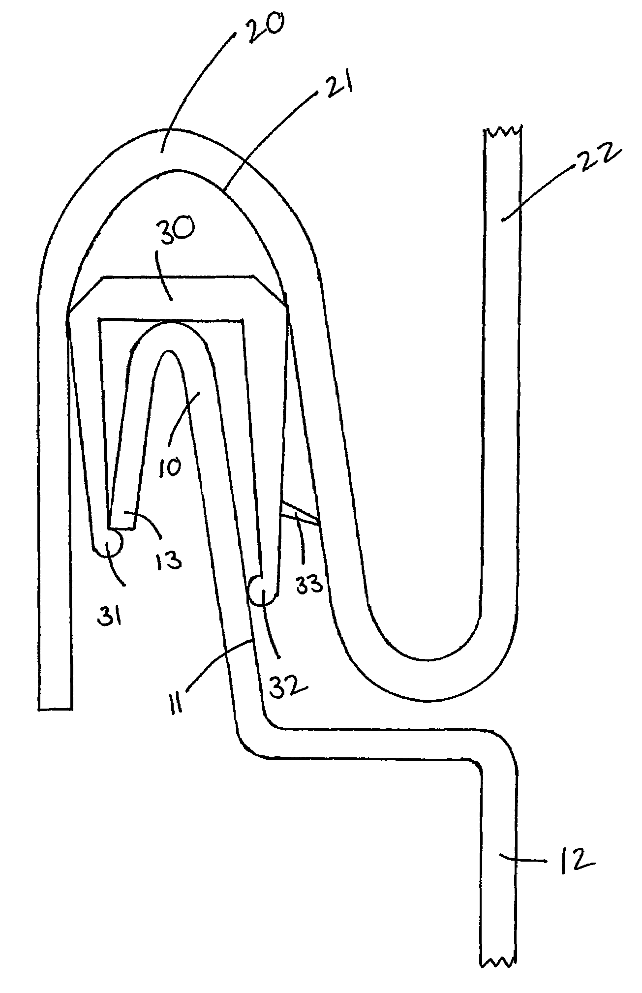
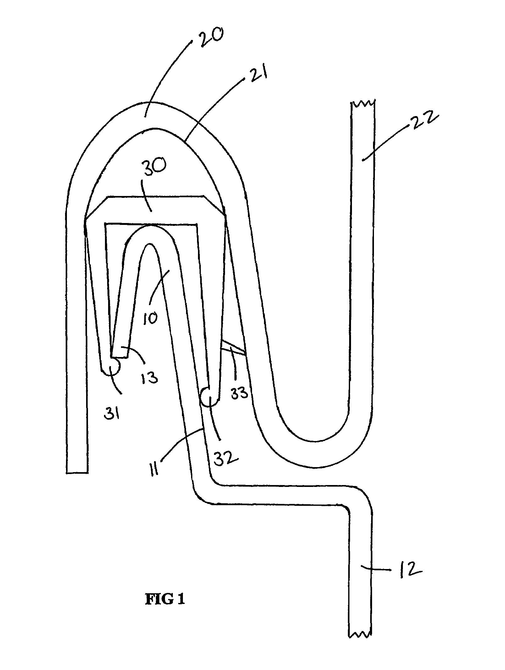
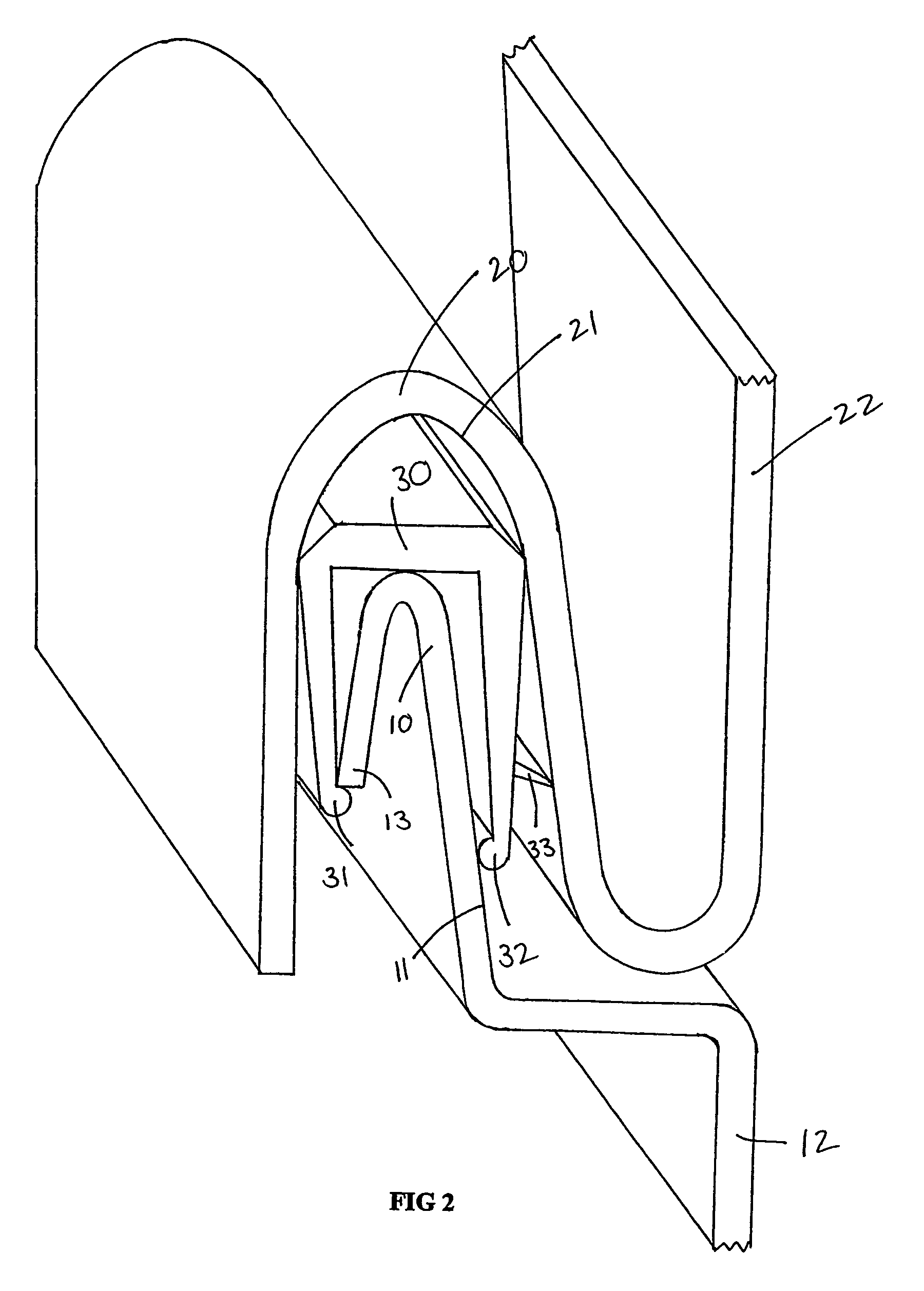
[0033]FIG. 1 shows a panel edge joint formed on opposing edges of a first panel 12 and second panel 22, said panels forming the boundary of a refrigeration unit cool room. The panel edge joint comprises a male part 10 extending along at least one edge of the first panel 12 and a corresponding female part 20 extending along at least one edge of a second panel 22. The male part 10 and the female part 20 sandwiching a deformable sleeve 30 therebetween.

[0034]The female part 20 has an inner contour 21 which corresponds with the outer contour of the male part. The dimensions of the parts allows for a loose fit of the parts with space between the outer male contour and inner female contour to accommodate the thickness of the deformable sleeve.

[0035]The deformable sleeve 30 is formed to have geometry such that the sleeve fits between the male and female parts to provide a tight fit. Preferably the geometry of the deformable sleeve 30 is slightly rectangular in comparison to the curvilinear ...


PUM


Abstract

A panel edge joint formed on opposing edges of a first panel (12) and second panel (22) for use in refrigeration units. The panel edge joint comprises a male part (10) extending along at least one edge of the first panel (12) and a corresponding female part (20) extending along at least one edge of second panel (22) wherein male part (10) comprises a deformable sleeve (30) forming an outer covering of male part (10). Engagement of male part (10) with female part (20) forms a seal between the first panel (12) and second panel (22).

Description

FIELD OF THE INVENTION[0001]The present invention relates to a panel edge joint for use in refrigeration units and in particular for use in cool rooms.BACKGROUND[0002]Refrigeration units are commonly used in commercial environments for storing perishable items at reduced temperatures for example providing a cool room. Typically, such units consist of metal panels sandwiching an insulating material defining the perimeter of the cool room area. The temperature within the cool room may be controlled by a refrigeration system comprising a heat pump to remove heat from the cool room, thereby lowering the temperature of the cool room.[0003]The heat pump operates against the natural flow of heat by removing the heat from the area to keep the temperature at a set point. Thus, when the temperature is higher inside or outside of the cool room, heat flows into the cooler area to overcome the difference in heat temperature gradient. These heat losses and gains affect the efficiency of the syste...

Claims


Application Information

Patent Timeline
Patent Type & Authority Patents(United States)
IPC IPC(8): E04B2/00E04H5/10F25D23/06
CPCE04H5/10Y10T403/54F25D23/063
Inventor LUCAS, JAMES WALTERLEE, TREVOR RODNEY
Owner LUCAS JAMES WALTER
Why Eureka
Try Eureka