Vehicle lamp

a technology for vehicle lamps and light guides, applied in the field of vehicle lamps, can solve the problems of difficult configuration, difficult to meet the outermost ends (outside ends) of the light guide lenses of the vehicle lamps to emit light, etc., to achieve the effect of reducing light loss

Inactive Publication Date: 2010-04-13
STANLEY ELECTRIC CO LTD
View PDF14 Cites 11 Cited by
  • Summary
  • Abstract
  • Description
  • Claims
  • Application Information

AI Technical Summary

Benefits of technology

[0015]In view of the foregoing characteristics, technical features, and other problems and reasons, the presently disclosed subject matter includes a vehicle lamp which can suppress dimensions in the depth direction and provide a large emission area with a simple configuration.
[0027]Thus, it is possible to provide a large emission area while suppressing the dimensions of the components other than the light-emitting parts in accordance with the present disclosure.
[0031]The light traveling inside the light guide lens with total reflection can produce a prismatic effect at the thickness changing portions of the lens which have differences in lens thickness. Because of these thickness changing portions, the presently disclosed subject matter can include a lamp that can be configured to provide a solid-looking and crystalline-looking appearance when the lamp is turned off. When the lamp is turned on, the surface ends corresponding to the thickness changing portions can emit light to provide a block-like plurality of light emissions which effect has been previously unavailable in conventional lamps.
[0032]Moreover, the light guide lens can guide incident light to an area outside the vehicle through total reflection when its end faces excluding the incident surface opposed to the light source unit are tilted with respect to the outlet surface, by a tilt angle of approximately 45° (in a particular example). Consequently, the presently disclosed subject matter can reduce light loss at the end faces.

Problems solved by technology

Accordingly, even if light guide lenses are provided on the light sources, this new structure and design has made it difficult for the outermost ends (outside ends) of the light guide lenses of the vehicle lamps to emit light.
Vehicle lamps that can satisfy such demand, however, can be difficult to configure.
Nevertheless, in vehicle lamps having such configurations, the amount of light incident on the light guide lens is small, and therefore the light guide lens looks dim when the light guide lens is observed from outside of the vehicle.
In addition to this, with the structure of utilizing total reflection inside the light guide lens to emit light in a lateral direction with respect to the direction of incidence of the light from the light source, light loss increases since the light emitted from the end face of the light guide lens is unused.
However, since these prisms look like a reflecting surface when observed from the light emission side, it is difficult for conventional light guide lenses to provide a crystalline look.
Furthermore, since such light guide lenses are intended for uniform light emission or so-called plane emission, it is difficult to provide a distinctive appearance in light emission.

Method used


Image

  • Vehicle lamp
  • Vehicle lamp
  • Vehicle lamp

Examples


Embodiment Construction

[0047]A description will now be given of exemplary embodiments of vehicle lamps made in accordance with principles of the presently disclosed subject matter with reference to FIGS. 1 to 12.

[0048]Note that in the following exemplary embodiments the vertical, horizontal, front-to-rear directions and the like are appropriately set on the basis of the respective drawings.

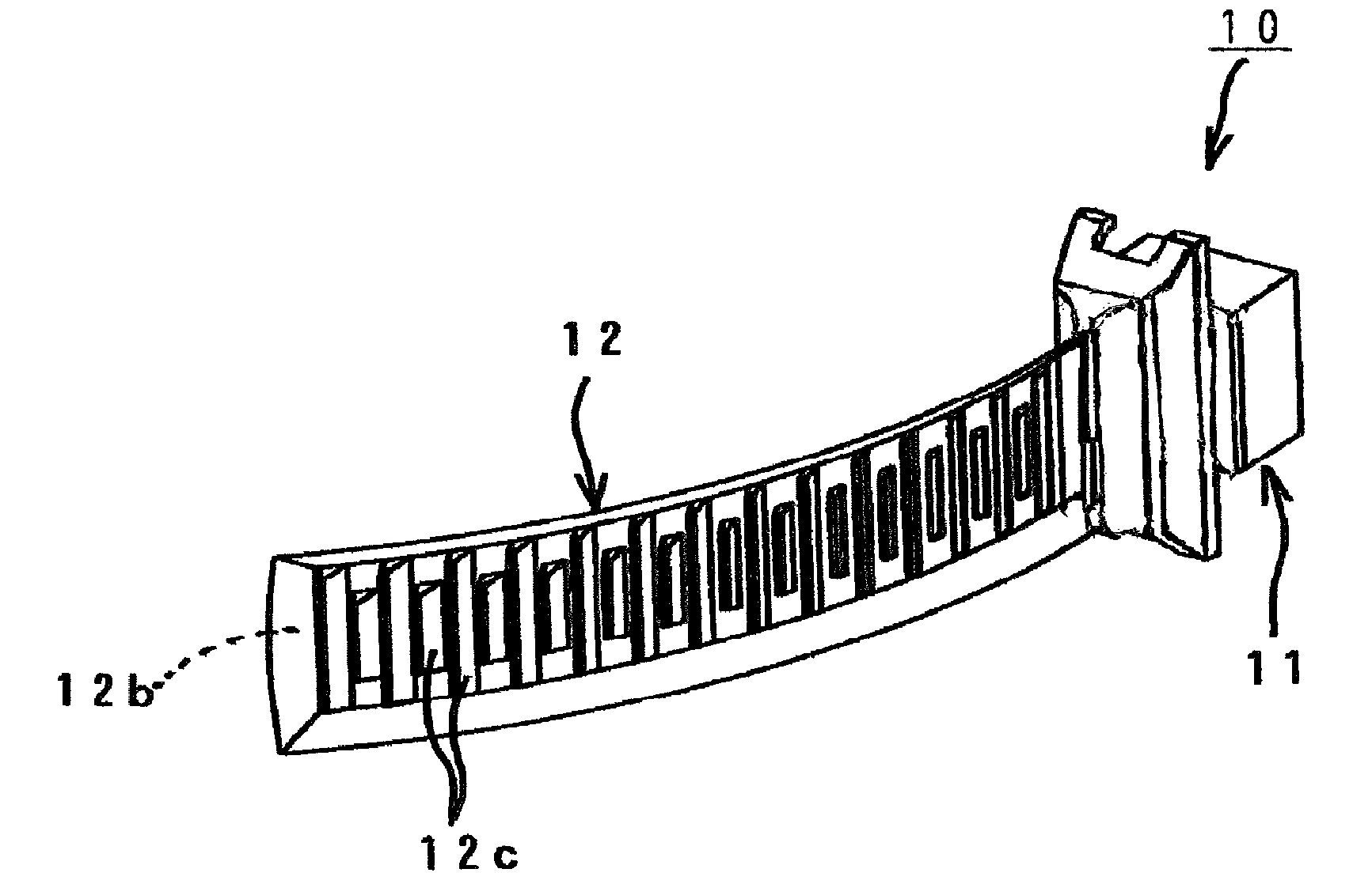
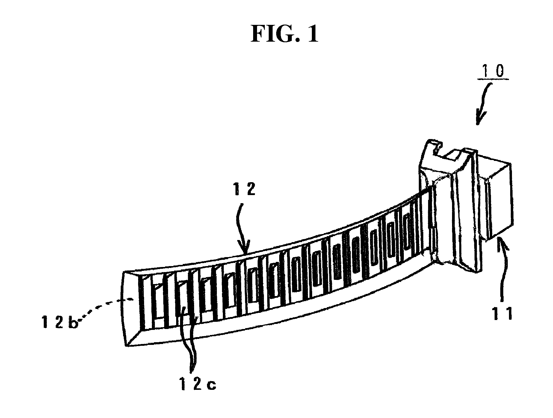
[0049]FIGS. 1 and 4 show the configuration of a first exemplary embodiment of a vehicle lamp made in accordance with principles of the presently disclosed subject matter.

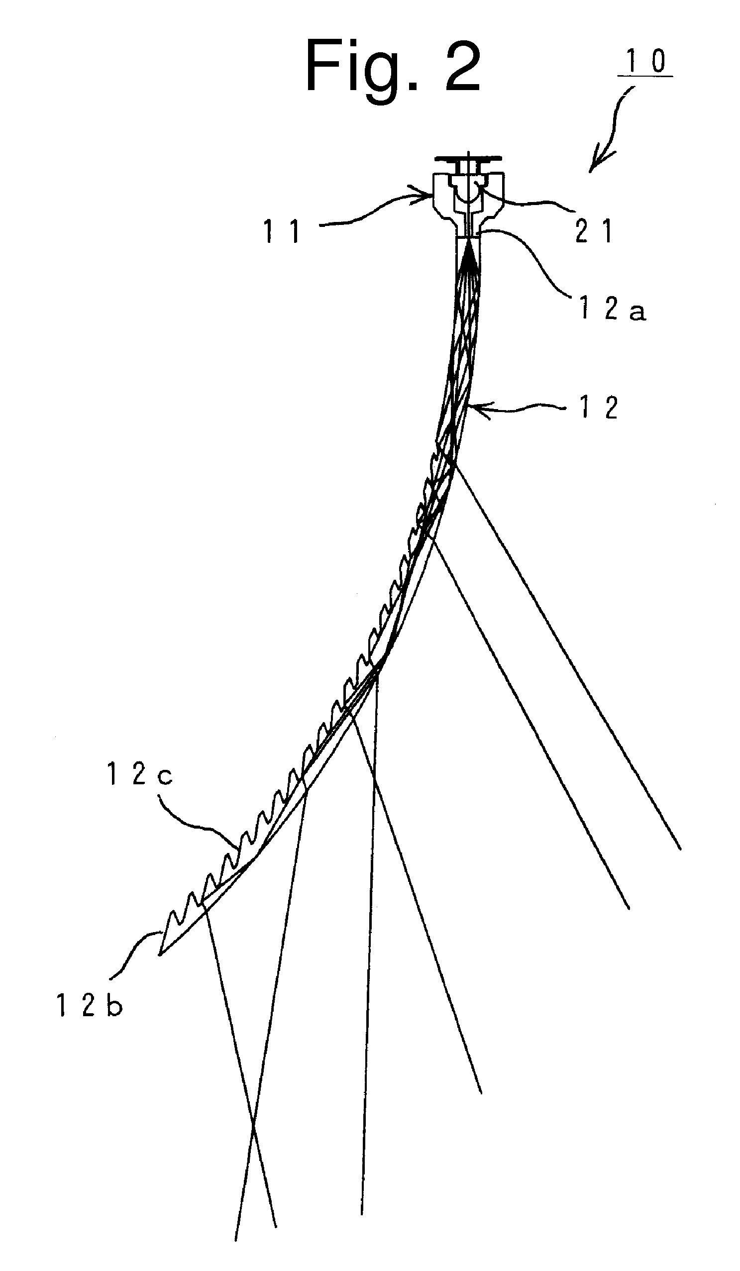
[0050]In FIGS. 1 to 4, the vehicle lamp 10 is a signal lamp such as a vehicle position lamp, and can include a light source unit 11 and a light guide lens 12.

[0051]As shown in FIGS. 5 and 6, the light source unit 11 can include at least one (one, in the shown example) LED light source 21 and a pair of fitting members 22 and 23 which constitute a conversion part.

[0052]The LED light source 21 can be a commercially available general-purpose LED light sourc...


PUM


Abstract

A vehicle lamp can suppress dimensions in the depth direction and provide a large emission area with a simple configuration, and has a light-emitting surface of wraparound configuration with impressive appearance and aesthetic qualities. The vehicle lamp can include a light source unit and a light guide lens. The light source unit can include a light source, and a converting part for converting light from the light source to a narrow width light. The conversion part has an emission area for emitting the converted light. The light guide lens can include one end face having a shape corresponding to the emission area of the conversion part, a thin plate-like light guiding portion for guiding the incident light, and another end face being a farthest part away from the incident surface. The light guide lens guides the incident light toward the other end face and emits the guided light from a predetermined surface thereof as it travels on its way through the lens.

Description

[0001]This application claims the priority benefit under 35 U.S.C. §119 of Japanese Patent Application No. 2007-065833 filed on Mar. 14, 2007, which is hereby incorporated in its entirety by reference.BACKGROUND[0002]1. Technical Field[0003]The presently disclosed subject matter relates to a vehicle lamp to be used as various types of lamps intended for a vehicle, such as a vehicle position lamp.[0004]2. Description of the Related Art[0005]In recent years, automobile and vehicle design has shifted to forms in which the four corners of the vehicle body are cut away obliquely and to a larger extent as compared to previous designs.[0006]Vehicle lamps that are to be mounted near the four corners of the vehicle body are therefore shaped to wrap around these body portions, and even the fender area of the vehicle body. Accordingly, even if light guide lenses are provided on the light sources, this new structure and design has made it difficult for the outermost ends (outside ends) of the l...

Claims


Application Information

Patent Timeline
Patent Type & Authority Patents(United States)
IPC IPC(8): F21V9/00H01L33/58H01L33/60
CPCF21S48/215F21S48/2243F21S48/2262G02B6/0038F21S48/23F21V7/09G02B6/0031F21S48/2281F21S43/14F21S43/239F21S43/243F21S43/249F21S43/30
Inventor FUTAMI, TAKASHI
Owner STANLEY ELECTRIC CO LTD
Why Eureka
Try Eureka