Seam sealer applicator

a sealer and applicator technology, applied in the field of sealer applicators, can solve the problems of deteriorating the bond between the flooring and the underlayment, separating the flooring, and a particularly vulnerable location of the seal between adjacent sheets of flooring

Inactive Publication Date: 2010-04-13
MARTINEZ LEO
View PDF4 Cites 15 Cited by
  • Summary
  • Abstract
  • Description
  • Claims
  • Application Information

AI Technical Summary

Benefits of technology

[0012]The present invention is a new, improved seam sealer applicator that eliminates many of the disadvantages associated with conventional commercial flooring seam sealing applicators. The seam sealer tip of the present invention employs a narrow stainless steel fin in which a sealant dispensing slit is defined. The fin or keel from which the chemical sealant is dispensed will not break off like conventional plastic fins, even with the harder flooring surfaces now utilized in residential flooring installations. Consequently, the seam sealer tip of the invention will last far longer without degradation than conventional tips.
[0013]The flat face at the downstream end of the seam sealer tip body is oriented relative to the alignment of the body such that the sealant is dispensed while holding the tip at a relatively small angle tilted back from perpendicular alignment relative to the floor. This allows the tip to be held with one or more fingers wrapped around the tip body and with the tip held at an angle of only about twenty degrees from perpendicular orientation relative to the flooring. The seam sealer applicator tip can thereby be held much more comfortably in the hand of the flooring installer.
[0014]Furthermore, downward pressure can be applied by holding the tip in a number of different positions between the fingers of the installer. This allows the installer to shift finger positions from time to time, thus resulting in far less fatigue to the installer's hand. Also, the configuration of the tip avoids the necessity for applying constant downward pressure by the index fingertip of the installer. This not only reduces finger fatigue, but avoids the excessive contact by the installer's index finger with the seam sealant.

Problems solved by technology

The seams between adjacent sheets of flooring represent a particularly vulnerable location in the flooring installation.
That is, although flooring installers attempt to abut adjacent sheets of flooring tightly against each other, there is always a seam between adjacent flooring sheets.
This often results in a deterioration of the bond between the flooring and the underlayment.
Such deterioration results in a separation of the flooring from the underlayment where the edges of the sheets of flooring abut.
As the surfaces of flooring goods utilized in residential flooring have improved and become more durable, conventional seam sealing applicators have become less and less satisfactory.
While this device is quite acceptable for many types of flooring, it has been found that the fin tends to break off when this applicator is utilized with the harder, more durable types of flooring now increasingly utilized in residential floors.
Also, even when utilized on softer flooring materials, a great deal of pressure is required to maintain the fin in the crevice between the adjacent sheets of flooring.
A constant application of pressure by an installer using the index finger of one hand is fatiguing and also exposes the installer's index finger to the caustic effect of the seam sealing adhesive.
In addition, the bead of sealant created is typically inordinately wide, thus leading to an unsightly appearance of the flooring on the edges adjacent the seam interface.
However, a great deal of downward force is required in order to force the vertical leg of the T-shaped tip into the crevice between the adjacent sheets of flooring.
This creates considerable fatigue.
It also exposes the index finger to an excessive amount of caustic sealant chemicals.
Furthermore, the metal flanges of the tip tend to scrape and gouge the surface of the flooring on both sides of the seam between the flooring sheets.
While this device is effective for properly dispensing sealants deep into the seam, it tends to be self-sharpening.
That is, as the device is used the depending leg of the applicator tip becomes sharper and sharper and tends to cut too deeply into the material.
Also, this device, like many other conventional seam sealer applicators, requires an inordinate, fatiguing amount of force applied by only the installer's index finger of one hand.

Method used


Image

  • Seam sealer applicator
  • Seam sealer applicator
  • Seam sealer applicator

Examples


Embodiment Construction

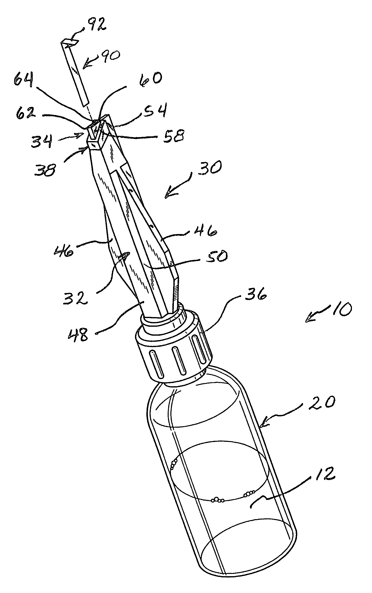
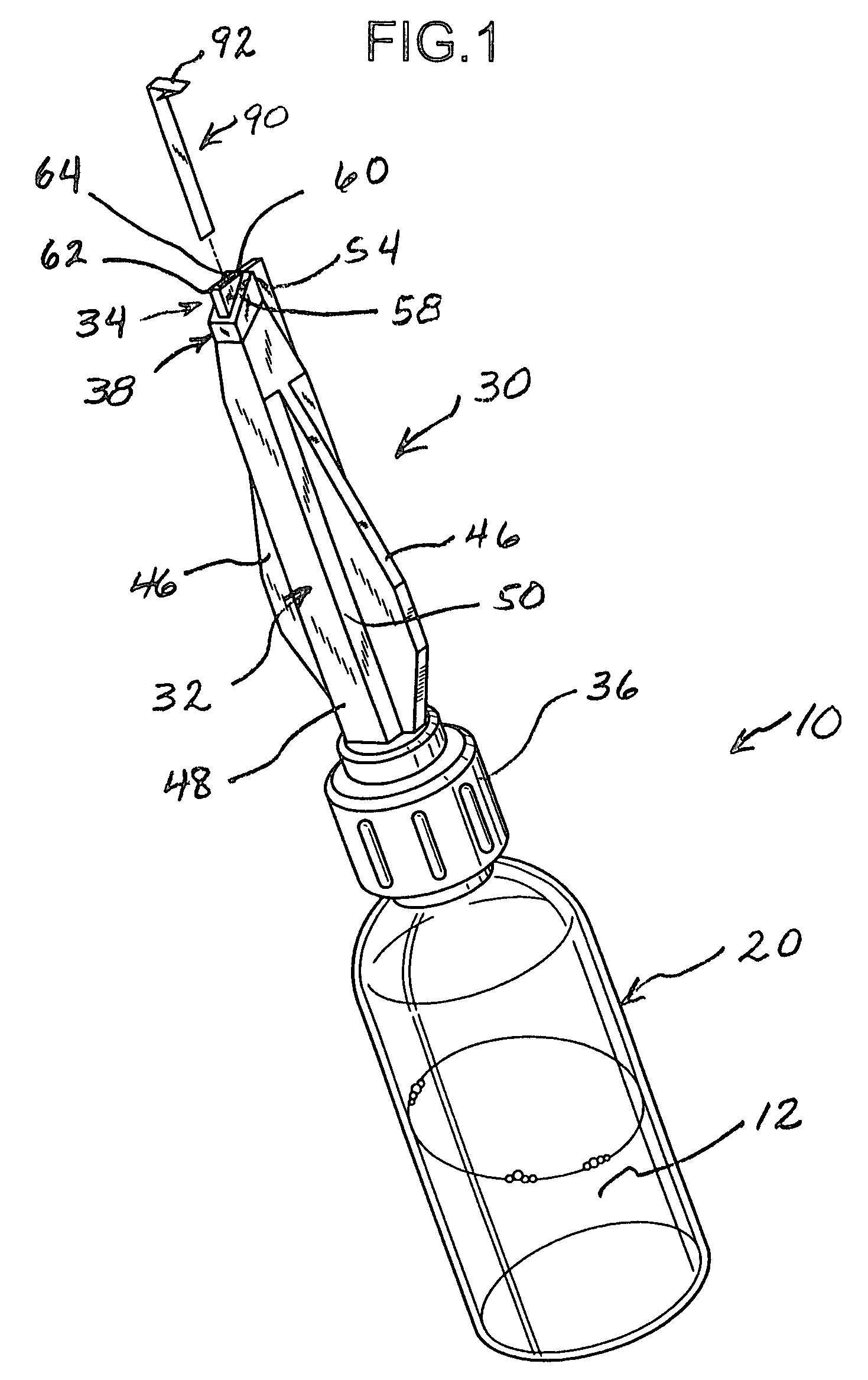
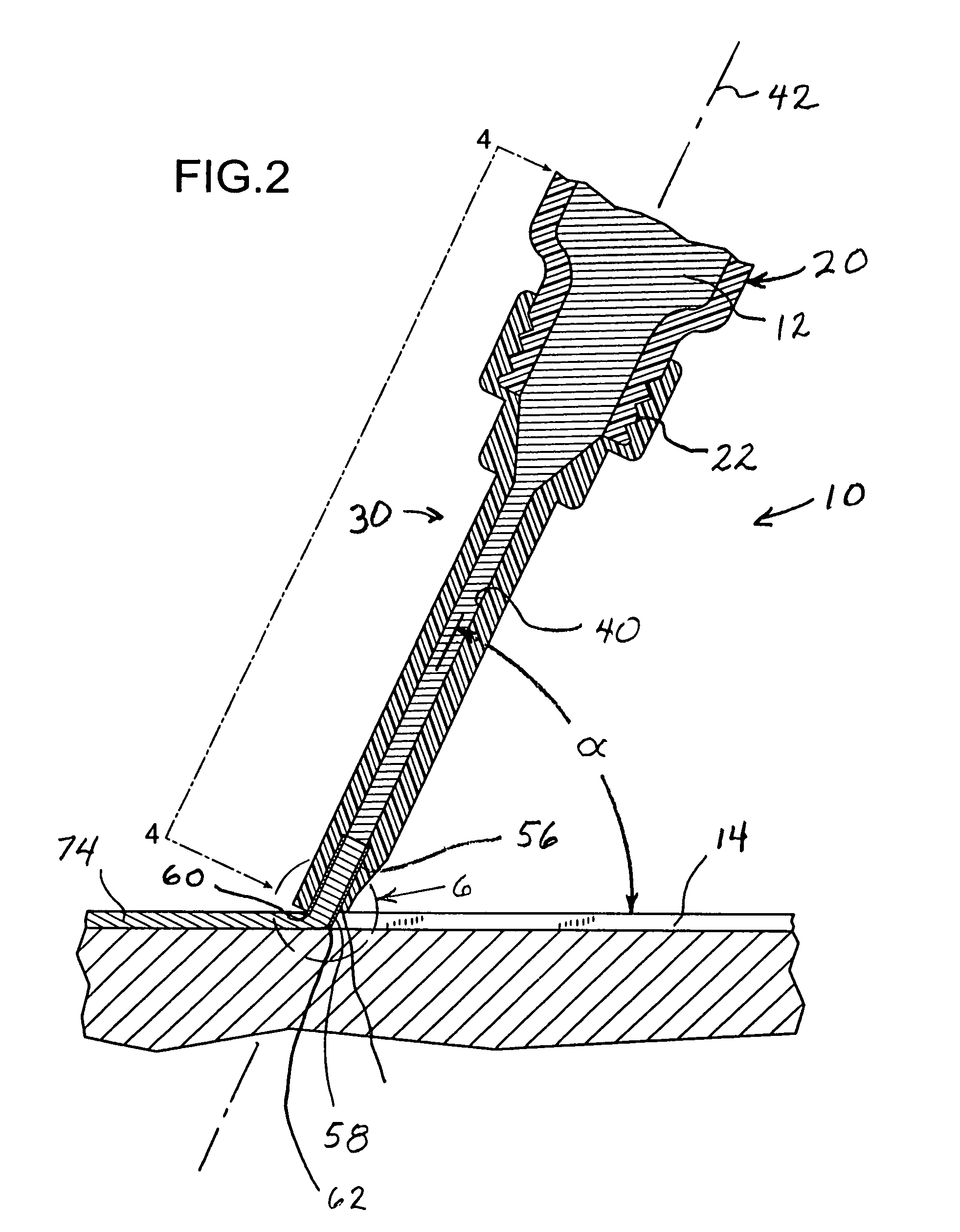
[0041]FIG. 1 illustrates a seam sealer applicator 10 for dispensing chemical sealant adhesive in liquid form, indicated at 12, into seams 14 between adjacent sheet of flooring 16 and 18, as illustrated in FIGS. 2 and 7-10. As shown in FIG. 1, the seam sealer applicator 10 is comprised of a hollow, plastic reservoir 20, which is preferably a hollow plastic bottle having a threaded neck 22, visible in FIG. 2. The threaded neck 22 of the reservoir bottle 20 forms an outlet from the reservoir 20.

[0042]The applicator 10 is also comprised of a seam sealer applicator tip 30 which has a hollow, rigid, plastic body 32 and a narrow, hollow stainless steel insert 34. The plastic body 32 has a proximal, upstream end 36 formed as an internally threaded socket that screws onto the threaded neck 22 of the reservoir bottle 20, and an opposite, downstream, distal end 38. Because it is hollow, the plastic body 32 forms a flow duct 40 therethrough that defines a straight, linear flow path that is at l...


PUM


Abstract

A seam sealing applicator for dispensing chemical sealant into seams between adjacent sheets of flooring is comprised of a sealant reservoir mounted atop an improved seam sealer applicator tip. The applicator tip of the invention has an elongated, hollow, rigid plastic body with a pair of laterally projecting wings or flanges between its proximal end which receives the sealant reservoir and its opposite, distal sealant dispensing end. The distal end of the plastic body terminates in a flat face, preferably oriented at an angle of about seventy degrees relative to the alignment of the linear sealant delivery duct formed within the body. A thin, hollow, narrow metal insert is set into the distal end of the body. A keel or fin portion of the metal insert protrudes beyond the flat face and projects into a seam between adjacent sheets of flooring. The fin portion of the metal insert defines a thin, narrow, dispensing slit through which sealant may be dispensed deep into the seam between sheets of adjacent flooring. A tracking sight ridge is preferably formed on the front of the applicator tip at the distal end thereof, directly above the flat sealant application flow face. The applicator tip body is at least three inches in length so that it can be gripped by the hand of the installer in a variety of different ways.

Description

BACKGROUND OF THE INVENTION[0001]1. Field of the Invention[0002]The present invention relates to devices for applying chemical sealants to seams between adjacent sheets of flooring.[0003]2. Description of the Prior Art[0004]In the flooring trade sheets of flooring formed of linoleum and other thermoplastic or plastic composition materials are laid in relatively large sections, side-by-side and secured one by one with a chemical adhesive to a floor underlayment. The seams between adjacent sheets of flooring represent a particularly vulnerable location in the flooring installation. That is, although flooring installers attempt to abut adjacent sheets of flooring tightly against each other, there is always a seam between adjacent flooring sheets. Dirt and moisture can penetrate the seam and seep beneath the flooring sheets. This often results in a deterioration of the bond between the flooring and the underlayment. Such deterioration results in a separation of the flooring from the und...

Claims


Application Information

Patent Timeline
Patent Type & Authority Patents(United States)
IPC IPC(8): B43K29/00
CPCB05C17/00503B05C17/00516E04F21/165B65D47/42B05C17/10
Inventor MARTINEZ, LEO
Owner MARTINEZ LEO
Why Eureka
Try Eureka