Apparatus for preventing vacuum of scroll compressor

a scroll compressor and vacuum prevention technology, applied in machines/engines, liquid fuel engines, positive displacement liquid engines, etc., can solve the problems of degrading compressor efficiency and increasing the production cost of fixed scrolls b>30/b>, so as to prevent burrs or foreign materials from being generated, smooth sliding valve operation, and enhancing reliability and efficiency of compressors

Active Publication Date: 2010-04-13
LG ELECTRONICS INC
View PDF8 Cites 22 Cited by
  • Summary
  • Abstract
  • Description
  • Claims
  • Application Information

AI Technical Summary

Benefits of technology

[0017]Therefore, an object of the present invention is to provide an apparatus for preventing vacuum of a scroll compressor capable of smoothly operating a sliding valve and enhancing a reliability and an efficiency of the compressor by preventing burr or foreign materials generated when a bypass channel is mechanically processed from remaining at a refrigerant channel and by preventing oil introduced into the bypass channel from excessively remaining at the bypass channel.
[0018]Another object of the present invention is to provide an apparatus for preventing vacuum of a scroll compressor capable of simplifying a fabrication process and reducing a production cost by reducing a defective proportion.
[0019]To achieve these and other advantages and in accordance with the purpose of the present invention, as embodied and broadly described herein, there is provided an apparatus for preventing vacuum of a scroll compressor, comprising: a casing having a hermetic space divided into a suction chamber of a low pressure and a discharge chamber of a high pressure; a fixed scroll fixedly installed between the suction chamber of the casing and the discharge chamber, having a compression chamber that consecutively moves by being engaged with an orbiting scroll, having an outlet through which a refrigerant compressed in the compression chamber is discharged to the discharge chamber, and having a bypass hole through which the suction chamber of the casing is connected to the discharge chamber; a valve block having an inner channel through which the bypass hole of the fixed scroll is connected to the discharge chamber of the casing and fixedly installed at the fixed scroll; and a valve member disposed between the bypass hole of the fixed scroll and the inner channel of the valve block, for opening between the bypass hole and the inner channel thereby supplying a refrigerant of the discharge chamber to the suction chamber when a pressure of the compression chamber is lowered into a pressure less than a certain pressure, and for closing between the bypass hole and the inner channel thereby preventing the refrigerant of the discharge chamber from backflowing into the suction chamber when the compression chamber maintains a certain pressure.

Problems solved by technology

First, the valve hole 32 is concaved by a certain depth at an outer circumferential surface of the plate 31 of the fixed scroll 30 towards a center of the plate 31, and the middle pressure channel 34 or the discharge pressure channel 35 is connected to the valve hole 32. As the result, burr generated when the middle pressure channel 34 and the discharge pressure channel 35 are mechanically processed remains in the valve hole 32 thereby to serve as an obstacle when the sliding valve 51 is operated.
Second, oil and refrigerant inside the compression chamber P are introduced into the valve hole 32 through the middle pressure channel 34 connected to the valve hole 32, and then remain in the valve hole 32 thereby to serve as an obstacle when the sliding valve 51 is operated.
Third, since the valve hole 32 is formed at a lateral wall of the fixed scroll 30 in a horizontal direction, a processing of the valve hole 32 is difficult, a defective proportion in processing the fixed scroll 30 is increased, and thus a production cost for the fixed scroll 30 is increased. Furthermore, since a gap between the valve hole 32 and the sliding valve 51 is increased due to an inaccurate dimension of the valve hole 32, a refrigerant inside the discharge chamber S2 is leaked thereby to degrade an efficiency of the compressor.

Method used


Image

  • Apparatus for preventing vacuum of scroll compressor
  • Apparatus for preventing vacuum of scroll compressor
  • Apparatus for preventing vacuum of scroll compressor

Examples


Embodiment Construction

[0032]Reference will now be made in detail to the preferred embodiments of the present invention, examples of which are illustrated in the accompanying drawings.

[0033]Hereinafter, an apparatus for preventing vacuum of a scroll compressor according to the present invention will be explained in more detail with reference to the attached drawings.

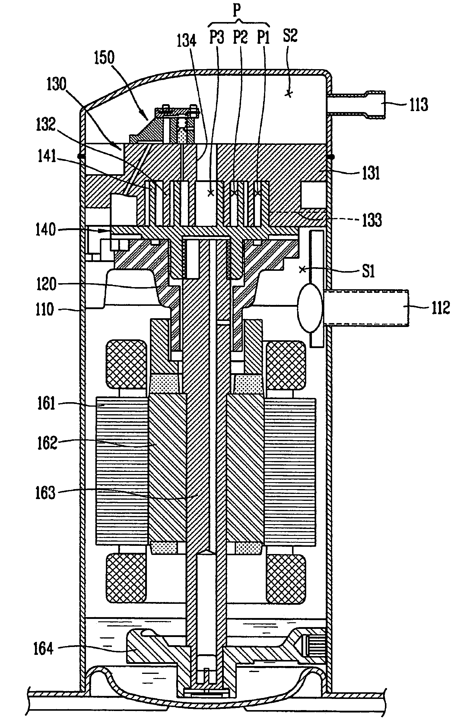
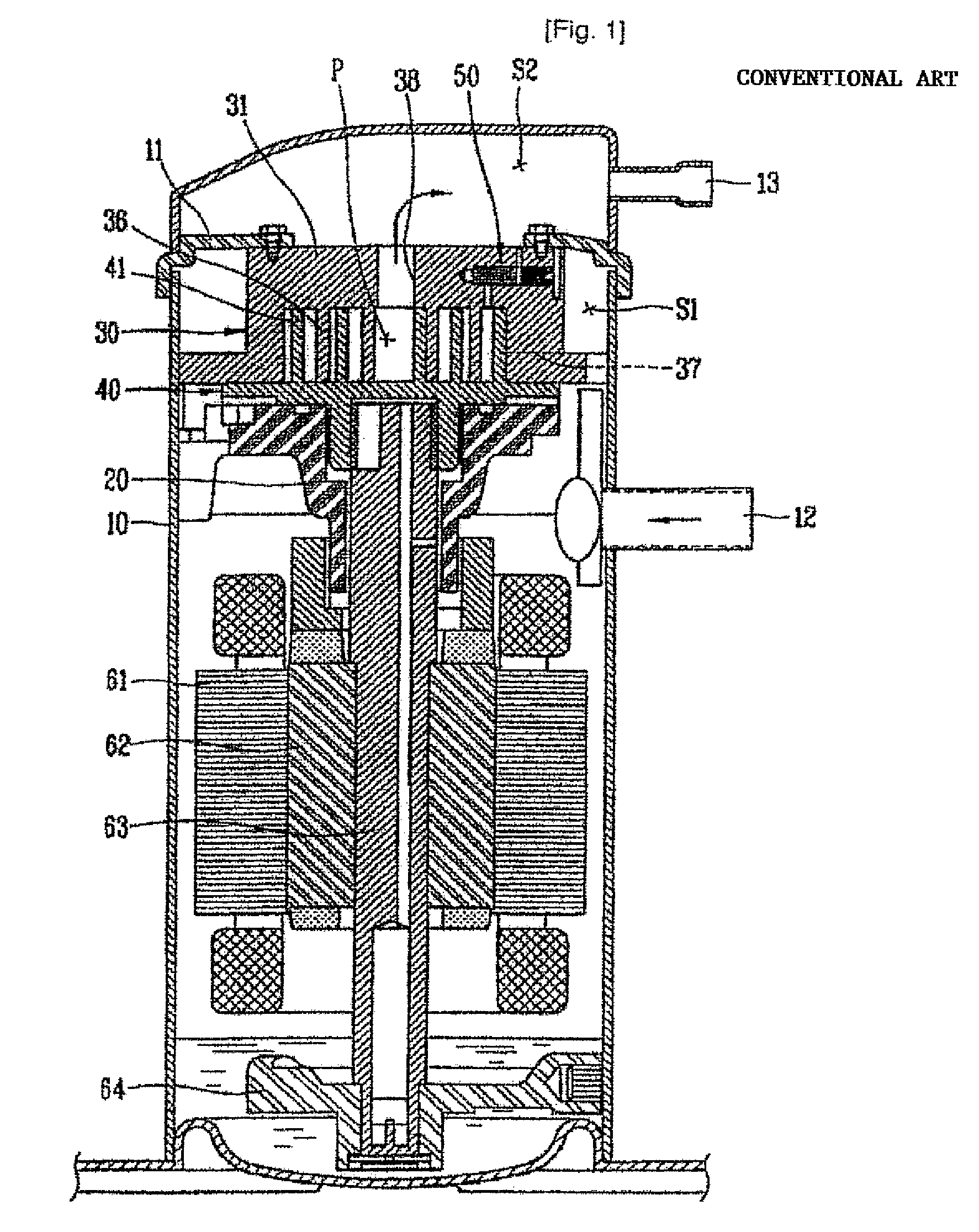
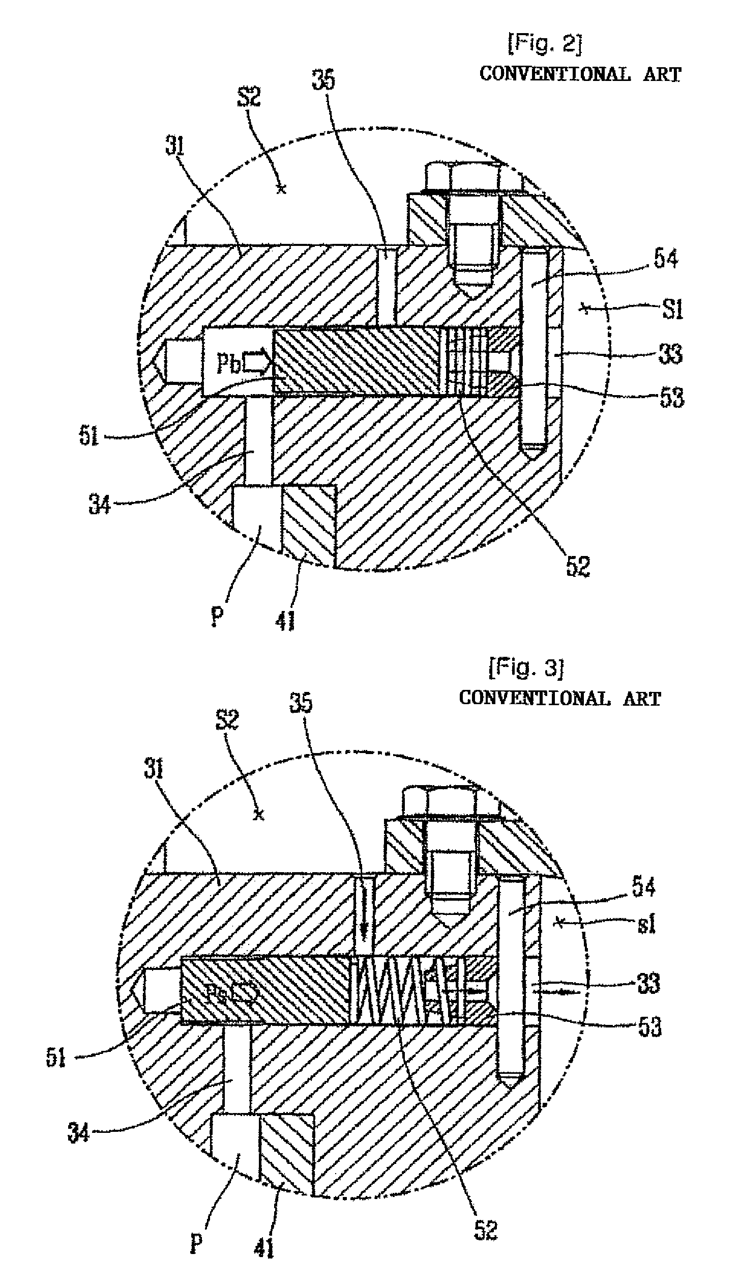
[0034]FIG. 4 is a sectional view showing a scroll compressor having an apparatus for preventing vacuum of a scroll compressor according to a first embodiment of the present invention, FIG. 5 is a sectional view showing the apparatus for preventing vacuum of a scroll compressor according to the present invention by enlargement, FIG. 6 is a sectional view showing an operation state of a vacuum preventing unit when the scroll compressor is normally driven according to the present invention, and FIG. 7 is a sectional view showing an operation state of the vacuum preventing unit when the scroll compressor is driven at a high vacuum state according ...


PUM


Abstract

An apparatus for preventing vacuum of a scroll compressor is provided. The apparatus includes a fixed scroll having a bypass hole, through which a suction chamber of a casing is connected to a discharge chamber of the casing; a valve block having an inner channel, through which the bypass hole of the fixed scroll is connected to the discharge chamber of the casing, and fixedly installed at the fixed scroll; and a valve member disposed between the bypass hole of the fixed scroll and the inner channel of the valve block. Since the apparatus is assembled at an outer periphery of the fixed scroll, a processing error of the fixed scroll is prevented, thereby reducing production costs. Also, since foreign materials generated when a refrigerant channel is processed do not remain in a valve hole, the valve member is prevented from being mal-operated, productivity is enhanced, and fabrication costs reduced.

Description

[0001]This application is the national phase under 35 U.S.C. §371 of PCT International Application No. PCT / KR2006 / 001209 which has an International filing date of Mar. 31, 2006, which designated the United States of America.TECHNICAL FIELD[0002]The present invention relates to a scroll compressor, and more particularly, to an apparatus for preventing vacuum of a scroll compressor capable of preventing a compressor from being driven in a vacuum state by flowing a refrigerant discharged from a high pressure chamber into a compression chamber when the compression chamber becomes a vacuum state during an operation.BACKGROUND ART[0003]In a scroll compressor, an orbiting scroll that performs an orbit movement by a crank shaft is provided with an orbit wrap of an involute shape thereby to form a compression chamber that consecutively moves with a fixed wrap of an involute shape of a fixed scroll. As the orbiting scroll performs an eccentric orbit movement by a rotation of the crank shaft, ...

Claims


Application Information

Patent Timeline
Patent Type & Authority Patents(United States)
IPC IPC(8): F03C2/00F04C18/00
CPCF04C18/0215F04C28/28F04C28/26F04C23/008
Inventor JOO, YOUNG-SENAM, TAE-HEEJIN, HONG-GYUNJU, YUN-SU
Owner LG ELECTRONICS INC
Why Eureka
Try Eureka