Ascertaining physical routing of cabling interconnects

a physical routing and communication system technology, applied in the field of communication networks, can solve the problems of high cost of space in these environments, high cost of network deployment and upgrading, and time-consuming task of determining the exact nature of interconnection errors, so as to reduce the time needed to troubleshoot cabling errors, the effect of easily and accurately determining the physical routing of cables

Inactive Publication Date: 2010-04-13
RPX CORP
View PDF24 Cites 9 Cited by
  • Summary
  • Abstract
  • Description
  • Claims
  • Application Information

AI Technical Summary

Benefits of technology

[0019]Advantageously, embodiments of the invention could be used by network and service providers to troubleshoot cabling interconnection problems of communications equipment, both electrical and optical interconnections, as well as other types of electronic systems in general. Important reductions in the time needed to troubleshoot cablings errors may be obtained by addressing the problem of easily and accurately determining the physical routing of cables, e.g. of interconnection systems in a Telco's CO.

Problems solved by technology

This evolution presents significant challenges to service and network providers, which attempt to serve their clients faster and better, by continuously enlarging and upgrading their networks with a view to serve a growing number of clients and to implement the latest advances in networking technologies.
Because the cost of space in these environments is high, the equipment is commonly organized in the most compact manner that is practical.
As a result, there is often a confusing collection of cabling running through the environment to interconnect the equipment within the respective location (office, cabinet, etc) both to other equipment within the location and to equipment outside of the location.
Network deployment and upgrading presents complex challenges to providers, one of which is managing interconnections between equipment of various size, make and functionality (also referred to here as systems) that make-up the network.
These techniques would also apply to cabling connections of electronic systems in general, in situations where there are numerous systems to be interconnected at a particular installation site and there are a very large number of electrical or optical cables interconnecting them, such that there exists a very real possibility of incorrect connections and wherein determining the exact nature of the interconnection errors would be a very onerous and time consuming task.
However, physical tags may become separated from the cables and the labels may be rendered illegible.
Further, locating a particular tag amongst a great many tagged cables in a crowded environment may be difficult.
Further, designing and manufacturing unique connectors for a very large number of cables is difficult and relatively costly because each can only serve a particular function and production runs tend to be in relatively small numbers.
However, this solution does not determine the physical layout of the cabling, which can be important for repairing or replacing faulty cables or to locate cables for various reasons, e.g. system relocation, site construction / maintenance, etc.
However, this solution is mostly concerned with locating the equipment in case of faults and does not address the problem of determining the physical layout of the cabling.

Method used


Image

  • Ascertaining physical routing of cabling interconnects
  • Ascertaining physical routing of cabling interconnects

Examples


Embodiment Construction

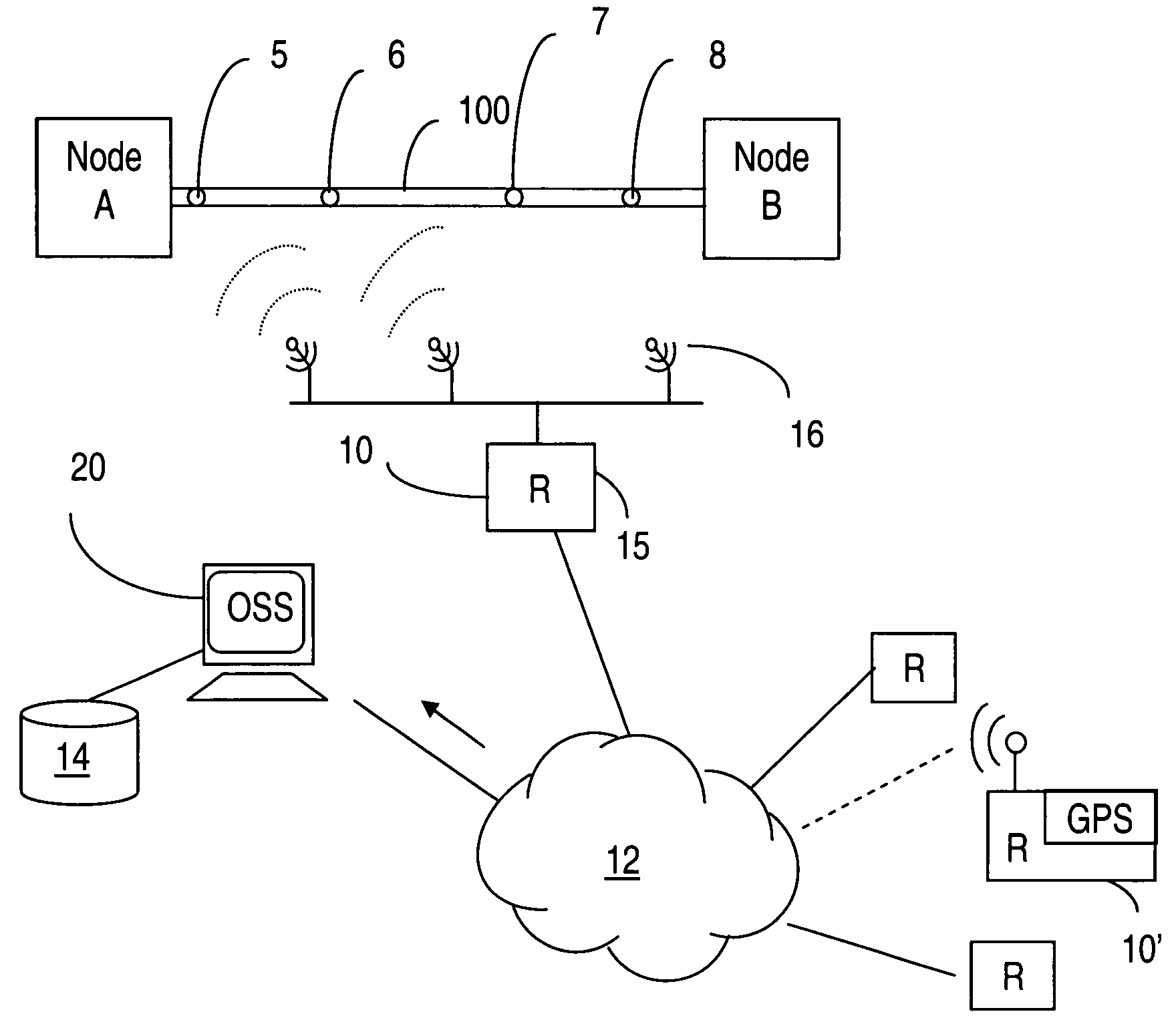
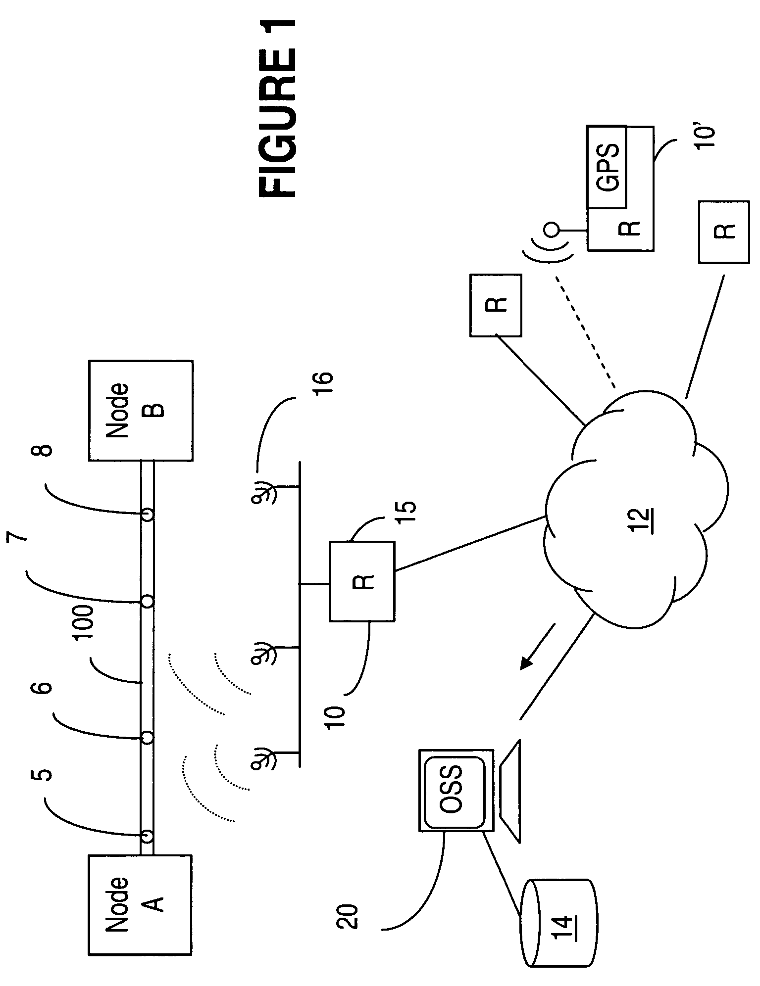
[0022]Referring to FIG. 1, a network of RFID readers is created for determining the physical layout of a cable plant and for communicating the corresponding layout information to a management system for cable management.

[0023]FIG. 1 illustrates tracing the physical routing of a cable 100 interconnecting two nodes, referred to as node A and node B. To this end, a cable 100 is equipped with RFID tags 5, 6, 7, 8 which are placed along it at periodic intervals. Information stored in each RFID tag would include, for example, a unique cable identifier and location of the RFID tag in the cable. The location of the RFID tag could be expressed as distance in meters from one end of the cable, or as a sequence number with respect to the sequence number of an adjacent RFID tag. In the case of the latter the RFID tags would be disposed at known equidistant, or periodic, intervals along the cable 100. A network 12 of remotely readable RFID readers 10-10′ collects cable routing information and com...


PUM


Abstract

In a communication network or networked system, cables that interconnect systems or parts of a system are provided with RFID tags embedded at periodic intervals along their lengths. A network of GPS-enabled RFID readers with triangulation capabilities enables the determination of the physical routing of cables within an area of interest. It also enables communication of the physical routing information to an operations support system for cable management.

Description

FIELD OF THE INVENTION[0001]The invention is directed to communication networks and in particular to a system and method for ascertaining the physical routing of cables interconnecting communication systems.BACKGROUND OF THE INVENTION[0002]Evolution of network technologies resulted in a world of interconnected networks where businesses and households are now amazingly close to each-other. The notion of “network” turns out to be central to our times: the Internet, LANs, WANs, enterprise networks, home networks, etc. are today interconnected over the World Wide Web, changing our lives and the way we do business. This evolution presents significant challenges to service and network providers, which attempt to serve their clients faster and better, by continuously enlarging and upgrading their networks with a view to serve a growing number of clients and to implement the latest advances in networking technologies.[0003]Typically, the equipment is situated in an environmentally hardened ...

Claims


Application Information

Patent Timeline
Patent Type & Authority Patents(United States)
IPC IPC(8): G08B13/14
CPCG01V15/00
Inventor LANGE, ANDREW SNOWDENNELSON, SCOTT WILLIAM
Owner RPX CORP
Why Eureka
Try Eureka