Electronic view finder utilizing an organic electroluminescence display

a view finder and electroluminescence display technology, applied in the field of view finders, can solve the problems of difficult user b>2100, image is therefore considerably difficult to recognize, and photograph objects, and achieve the effect of less power and high resolution

Inactive Publication Date: 2010-04-13
SEMICON ENERGY LAB CO LTD
View PDF79 Cites 60 Cited by
  • Summary
  • Abstract
  • Description
  • Claims
  • Application Information

AI Technical Summary

Benefits of technology

[0012]The present invention has been conceived taking the above-described problems into consideration, and it is an object of the invention to provide a view finder which consumes less power and which can present large images having a high resolution to users.

Problems solved by technology

In the case of the conventional view finder, an image on the view finder 2003 observed by a user 2100 is an image on the small liquid crystal panel 2003-1, and the image is therefore considerably hard to recognize because of its small size and low resolution.
As a result, in practice, it has been difficult for a user 2100 to photograph an object while observing an image of the same on the view finder 2003.
Therefore, when a video camera is used with such an external liquid crystal panel 2002 operated, there is a significant influence on the durability of the battery which is one of the most serious problems with a video camera for which out-door usability and portability is important.
However, the trend toward liquid crystal panels having greater sizes and higher resolutions has resulted in an increase in the power consumption of liquid crystal panels, and this is a significant problem for digital cameras which are intended for out-door use like video cameras.

Method used


Image

  • Electronic view finder utilizing an organic electroluminescence display
  • Electronic view finder utilizing an organic electroluminescence display
  • Electronic view finder utilizing an organic electroluminescence display

Examples


first embodiment

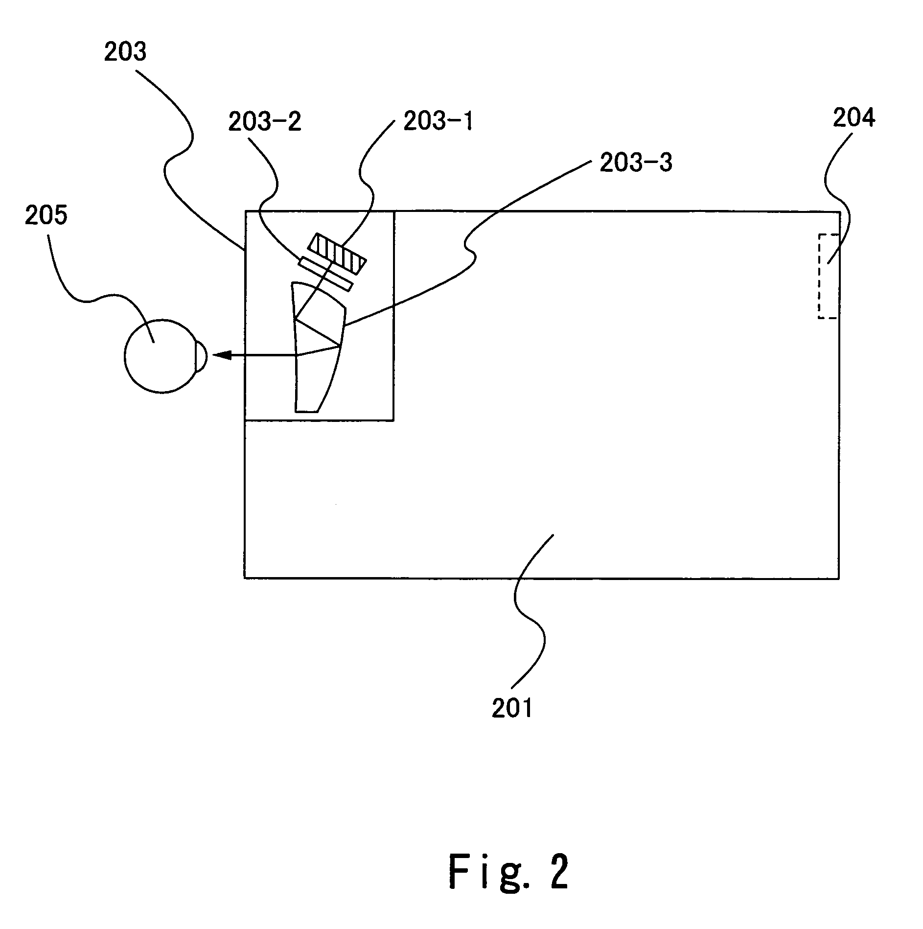
[0050]Refer to FIG. 2. FIG. 2 shows a view finder 203 according to the present embodiment incorporated in a video camera 201. 204 represents a lens. As shown in FIG. 2, the view finder 203 according to the present embodiment has a display element 203-1 and optical elements 203-2 and 203-3. Light emitted by the display element 203-1 impinges upon the optical element 203-2 through the optical element 203-3. The light incident upon the optical element 203-2 is reflected by reflecting surfaces of the optical element 203-3 to exit from a transmitting surface thereof and to then exit from the view finder 203. A user of the video camera 201 recognizes a magnified image by observing the light exiting the view finder 203 according to the invention.

[0051]Light incident upon the optical element 203-3 used in the view finder 203 of the present embodiment is reflected twice by the reflecting surfaces to exit from the transmitting surface. With the view finder 203 of the present embodiment, an im...

second embodiment

[0058]Refer to FIG. 4. FIG. 4 shows a view finder according to the present embodiment incorporated in a video camera 401. 404 represents a lens. As shown in FIG. 4, a view finder 403 according the present invention has a display element 403-1 and an optical element 403-2. The optical element 403-2 is an optical element such as a lens. Light emitted by the display element 403-1 impinges upon the optical element 403-3 to be magnified and emitted from the view finder 403. A user of the video camera 401 recognizes the magnified image by observing light exiting from the view finder 403 according to the invention.

[0059]With the view finder 403 of the present embodiment, an image displayed on the display element 403-1 is thus magnified by the optical element 403-2 and recognized by an eye 405 of a user. This allows the user to check a magnified image by observing the view finder 403 without observing an external display device.

[0060]A display element as described in the first embodiment is...

third embodiment

[0061]Refer to FIG. 5. FIG. 5 shows a view finder according to the present embodiment incorporated in a video camera 501. 504 represents a lens. As shown in FIG. 5, a view finder 503 according to the present embodiment has a display element 503-1 and an optical element 503-2. Light emitted by the display element 503-1 impinges upon the optical element 503-2. The light incident upon the optical element 503-2 is reflected by reflecting surfaces of the optical element 503-2 to exit from a transmitting surface thereof and to then exit from the view finder 503. A user of the video camera 501 recognizes a magnified image by observing the light exiting the view finder 503 according to the invention.

[0062]With the view finder 503 of the present embodiment, an image displayed on the display element 503-1 is thus magnified by the optical element 503-2 and recognized by an eye 505 of a user. This allows the user to check a magnified image by observing the view finder 503 without observing an e...


PUM


Abstract

A view finder according to the present invention has an electroluminescence display element which displays an image of an object, and an optical element which magnifies the image.

Description

BACKGROUND OF THE INVENTION[0001]1. Field of the Invention[0002]The present invention relates to a view finder and, more particularly, to a view finder used in a video camera or the like.[0003]2. Description of the Related Art[0004]Digital cameras and video cameras incorporating a CCD image pick-up element have recently been spreading as a result of a trend toward CCD image pick-up elements having higher resolution and smaller sizes. FIG. 8A is an external view of a conventional video camera.[0005]2001 represents a video camera body; 2002 represents a liquid crystal panel; 2003 represents a view finder; 2004 and 2005 represent operating switches; and 2006 represents a lens. In the video camera shown in FIGS. 8A and 8B, an image taken in through the lens 2006 is converted by the CCD image-pick up element into an image signal which is in turn recorded on a recording medium. The liquid crystal panel 2002 and view finder 2003 are display devices for displaying the image signal.[0006]As ...

Claims


Application Information

Patent Timeline
Patent Type & Authority Patents(United States)
IPC IPC(8): H04N5/222G09G3/20G09G3/22
CPCH04N5/23293H01L27/3244H10K59/12
Inventor YAMAZAKI, SHUNPEIYAMAZAKI, YUHAYASHI, KEISUKE
Owner SEMICON ENERGY LAB CO LTD
Why Eureka
Try Eureka