Multilink trunking for encapsulated traffic

a trunking and traffic technology, applied in the field of all, can solve the problems of poor frame distribution between links in a lag, and achieve the effect of greater variability

Inactive Publication Date: 2010-04-13
RPX CLEARINGHOUSE
View PDF18 Cites 29 Cited by
  • Summary
  • Abstract
  • Description
  • Claims
  • Application Information

AI Technical Summary

Benefits of technology

[0009]For a carrier network, a trunk can be established across the carrier network as a tunnelled path between a particular carrier source address and carrier destination address. The trunk can be used to carry many different services. Each service within a trunk can be represented by a Service ID or similar identifier. Allocating data frames to links using a distribution function which operates (‘hashes’) on a service, customer or user-specific identifier in the encapsulated data frame allows a better distribution of frames among the group of links. This is because the identifier varies for each service, or each customer or user. The identifier has much greater variability than the carrier source and destination addresses in the outer header of the encapsulated data frame. Distributing traffic by operating on the Service ID field is particularly advantageous as it also obeys the rule that all data frames associated with the same service (or application) should always be sent down the same link in the MLT group. This minimises jitter. Since the header format is defined (or will be defined) by the IEEE, it is easy to adapt current firmware to hash on a different part of the frame. Preferably, the encapsulation of the data frame occurs at the same OSI Layer as the original data frame, such as MAC-in-MAC or Pseudowire over MAC at OSI Layer 2.

Problems solved by technology

When the existing hashing algorithms outlined above are applied to MAC-in-MAC traffic they result in a poor distribution of frames between links in a LAG because the source and destination MAC addresses operated upon by those algorithms have a very limited address space, e.g. the several hundred addresses of the carrier network compared to many thousands of addresses for conventional Ethernet.

Method used


Image

  • Multilink trunking for encapsulated traffic
  • Multilink trunking for encapsulated traffic
  • Multilink trunking for encapsulated traffic

Examples


Embodiment Construction

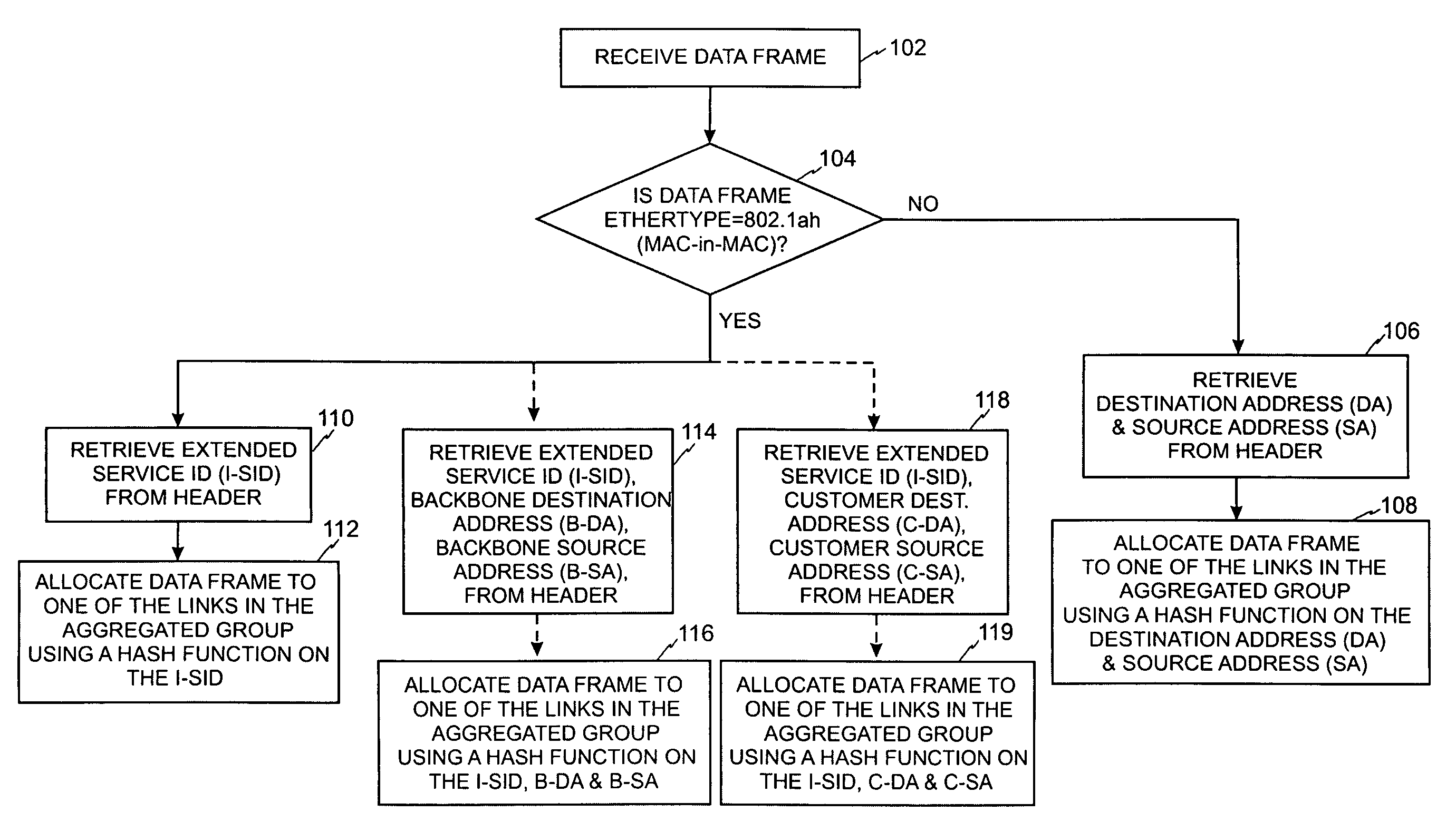
[0028]For the purpose of this description the term bytes and octets are used interchangeably.

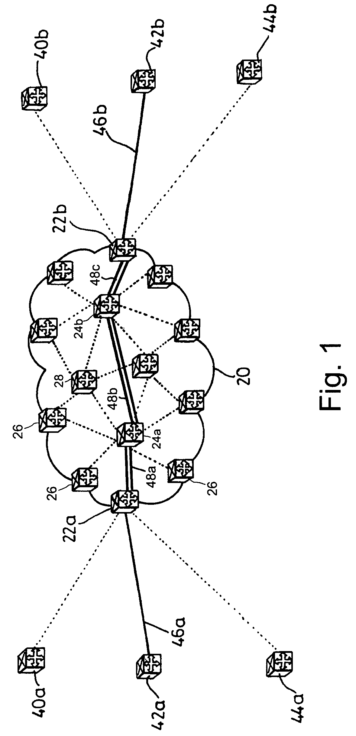
[0029]FIG. 1 shows an arrangement of Ethernet switches and communications links forming a carrier network. Carrier network cloud 20 comprises Ethernet switches 22a, 22b, 24a, 24b, 26 and 28. Ethernet switches 22a, 22b and 26 are located at the edges of carrier network 20, whereas Ethernet switches 24a, 24b, and 28 are located in the core network. Communications links (shown as straight lines) are provided between Ethernet switches 22a, 22b, 24a, 24b, 26 and 28. These communications links may be, for example, relatively long distance links over optical equipment such as SONET / SDH equipment with Ethernet interfaces using Generic Framing Procedure (GFP) (ITU-T Recommendation G.7041 / Y.1303). Although a carrier network is shown as an example of the type of network that the Ethernet switches can be used with, the invention is not limited to this. In addition, although core network switches 24a, 24...


PUM


Abstract

A node of a frame-based network has a group of outgoing links which are to be treated as an aggregated group of links. A frame distributor performs a distribution function on data frames which are intended for transmission on the group of links. The frame distributor determines if the data frame is an encapsulated data frame which forms part of a tunnelled traffic path across the network. If the data frame does form part of a tunnelled traffic path across the network, the frame distributor allocates the data frame to one of the group of links using at least part of an identifier from the header of the data frame. The identifier represents a service with which the data frame is associated, a customer or user of the data frame, or the tunnelled traffic path, which have greater variability than the backbone destination and source addresses.

Description

FIELD OF THE INVENTION[0001]This invention relates to allocating data frames to an aggregated group of links in a network.BACKGROUND TO THE INVENTION[0002]For many years now, telecommunications carriers have been deploying packet-switched networks in place of, or overlaid upon, circuit-switched networks for reasons of efficiency and economy.[0003]Link Aggregation (IEEE 802.3ad), also known as MultiLink Trunking (MLT) is a standardised way of bonding together groups of Ethernet links, called a Link Aggregation Group (LAG), to make them appear as a single higher-capacity link. MLT simplifies network operations by reducing the number of links that need to be managed and by improving redundancy. It is implemented by many vendors on existing hardware. MLT has been incorporated into the IEEE 802.3 standard at clause 34. The MLT standard defines a Frame Distributor which is responsible for taking outgoing frames of data from a Medium Access Control (MAC) client and transmitting them throug...

Claims


Application Information

Patent Timeline
Patent Type & Authority Patents(United States)
IPC IPC(8): H04L12/28
CPCH04L12/4633H04L45/245H04L12/4658Y02B60/33Y02D30/50
Inventor PARRY, SIMONFRISKNEY, ROBERT
Owner RPX CLEARINGHOUSE
Why Eureka
Try Eureka