Apparatus for pressing a covering onto a printing-unit cylinder for a rotary press

a technology of printing unit and cylinder, which is applied in the direction of printing presses, office printing, printing, etc., can solve the problems of increasing the number of hose lines and the cost of hose routing, and achieve the effect of low cost and low space requiremen

Inactive Publication Date: 2010-04-20
MANROLANAD AG
View PDF10 Cites 0 Cited by
  • Summary
  • Abstract
  • Description
  • Claims
  • Application Information

AI Technical Summary

Benefits of technology

[0006]It is an object of the invention to provide an apparatus for pressing a covering against a printing-unit cylinder, which apparatus is distinguished by a low space requirement and can be produced inexpensively. Moreover, a method is to be provided.
[0007]According to the invention, the carrier has a closed profile and a plurality of longitudinal channels within the closed profile. The channels are flow-connected to pressure spaces in the operating cylinder, and can be supplied with a pressure medium. The apparatus makes it possible to omit hose lines which are replaced by the channels of the carrier. Moreover, the closed profile makes possible to configure the carrier with a small cross section which saves space and weight. Furthermore, the carrier makes it possible to mount the operating cylinders with low expenditure. It is also possible to modify the apparatus in a simple manner for a different number of operating cylinders and pressure rollers and thus for printing-unit cylinders of different width. Overall, cost-saving manufacturing of the apparatus is possible for a wide variety of installation variants.

Problems solved by technology

In this apparatus, it is disadvantageous that the expenditure and space requirement for the routing of the hose lines rises with an increasing number of operating cylinders.

Method used


Image

  • Apparatus for pressing a covering onto a printing-unit cylinder for a rotary press
  • Apparatus for pressing a covering onto a printing-unit cylinder for a rotary press
  • Apparatus for pressing a covering onto a printing-unit cylinder for a rotary press

Examples


Embodiment Construction

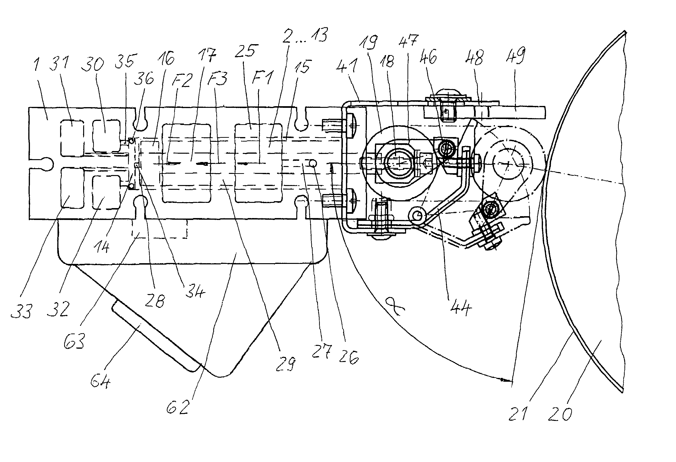
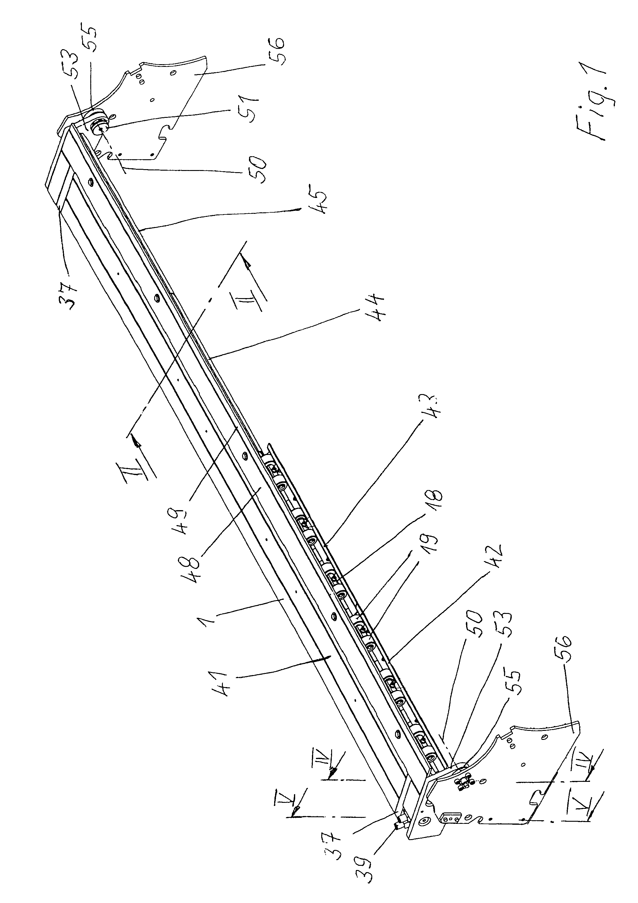
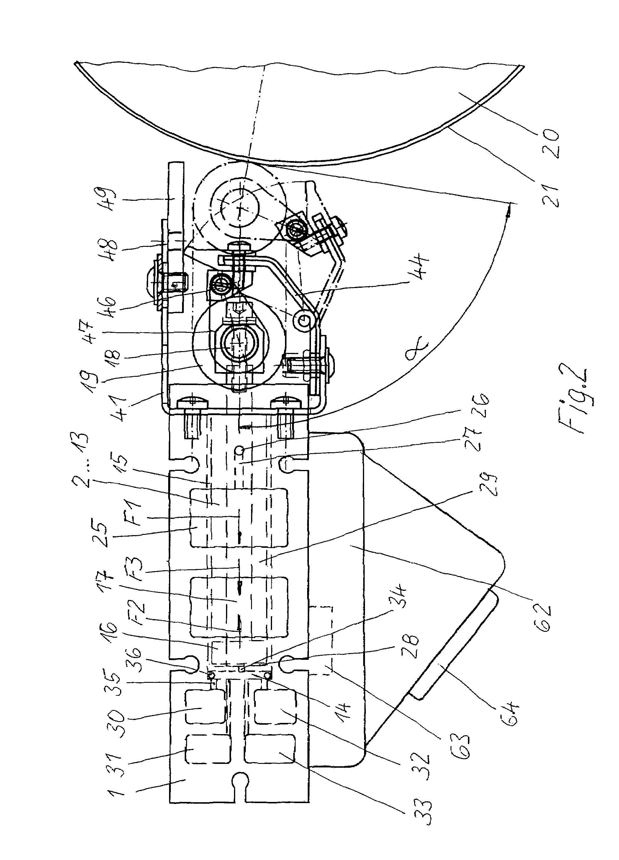
[0015]The apparatus shown in FIG. 1 includes a carrier 1 having a closed profile, as shown in FIG. 2. Arranged next to one another in its longitudinal direction, the carrier 1 has twelve operating cylinders 2 to 13 which are plugged and fastened into in each case one bore 14. Instead of the pneumatic operating cylinders 2 to 13, hydraulic operating cylinders could also be used. The operating cylinders 2 to 13 advantageously have a cup-shaped sleeve 15, in which a piston 16 together with the piston rod 17 are situated. An axle 18 is fastened to each piston rod 17, on which axle 18 two pressure rollers 19 are mounted rotatably (FIGS. 1, 6). Instead of this, only one pressure roller 19 could also be mounted in a fork, for example, on a piston rod 17.

[0016]The apparatus is arranged along a forme cylinder 20 which bears four printing formes 21 to 24 next to one another in the axial direction. FIG. 6 shows these printing formes 21 to 24 diagrammatically. Instead of on a forme cylinder, th...


PUM


Abstract

A plurality of longitudinal channels for supplying pressure medium are arranged within a carrier having a closed profile. A plurality of operating cylinders have pressure spaces which are flow-connected to the channels for moving the pressure rollers inward and outward in order to press coverings onto a printing unit cylinder.

Description

BACKGROUND OF THE INVENTION[0001]1. Field of the Invention[0002]The invention relates to an apparatus and a method for pressing a covering onto a printing-unit cylinder of a rotary press with the aid of at least one pressure roller which can be set against the printing-unit cylinder by means of an operating cylinder.[0003]2. Description of the Related Art[0004]U.S. Pat. No. 5,617,792 shows pressure rollers which are arranged along a forme cylinder on a carrier and can be set against a flexible printing forme which is situated on the forme cylinder by means of pneumatic operating cylinders. The pressure spaces of the operating cylinders are fed with compressed air via hoses.[0005]In this apparatus, it is disadvantageous that the expenditure and space requirement for the routing of the hose lines rises with an increasing number of operating cylinders.SUMMARY OF THE INVENTION[0006]It is an object of the invention to provide an apparatus for pressing a covering against a printing-unit c...

Claims


Application Information

Patent Timeline
Patent Type & Authority Patents(United States)
IPC IPC(8): B41F27/12
CPCB41F27/1206B41P2227/62B41P2227/11B41F27/12B41F27/00
Inventor KLAUSS, STEFFENKOPPELKAMM, GUNTERNAUMANN, REINHARDOERTEL, FRANK
Owner MANROLANAD AG
Why Eureka
Try Eureka