
Utility belt system

a belt system and utility technology, applied in the field of utility belt systems, can solve the problems of affecting the use of the belt, etc., and achieve the effects of convenient use, convenient and convenient separation and lifting, and quick and easy releas

Active Publication Date: 2010-04-20
PANOSIAN MICHAEL +3
View PDF12 Cites 26 Cited by
  • Summary
  • Abstract
  • Description
  • Claims
  • Application Information

AI Technical Summary

Benefits of technology

"The invention is a utility belt system that allows users to carry a plurality of objects on their belt. The system includes an elongated strap with a finger-gripping portion that makes it easy to grip and detach the objects from the belt. The system also includes a snap-lock that can be easily unlocked and released with the user's fingers. The technical effects of the invention include overcoming the disadvantages of prior art tool belts, being simple and economical to manufacture, being easy and convenient to use, being modular and customizable, and being convenient for users to add, remove, or exchange pouches or objects with."

Problems solved by technology

However, these tool bags offer only a limited range of adjustability, and pouches and tool holders can be easily knocked off of the belt, causing the nails, screws, bolts and / or tools to fall and possibly scatter.
This is particularly a problem when a tradesperson is working at elevated levels, above other people.
The known tool belts have also exhibited disadvantages in the ways they add, remove or interchange pouches or object-receiving receptacles.
When they have been removable, attaching or detaching them from the tool belt has been inconvenient, awkward and / or difficult, especially when the pouches or receptacles are large, bulky or heavy.
Such fasteners frequently make it to difficult, if not impossible, to detach the pouch, especially with only one hand while the other hand is occupied.
These tool belts are neither designed nor intended to facilitate attachment, detachment or exchange of pouches while working or in difficult working environments such as on a ladder or crouching in a tight space.

Method used


Image

  • Utility belt system
  • Utility belt system
  • Utility belt system

Examples


Embodiment Construction

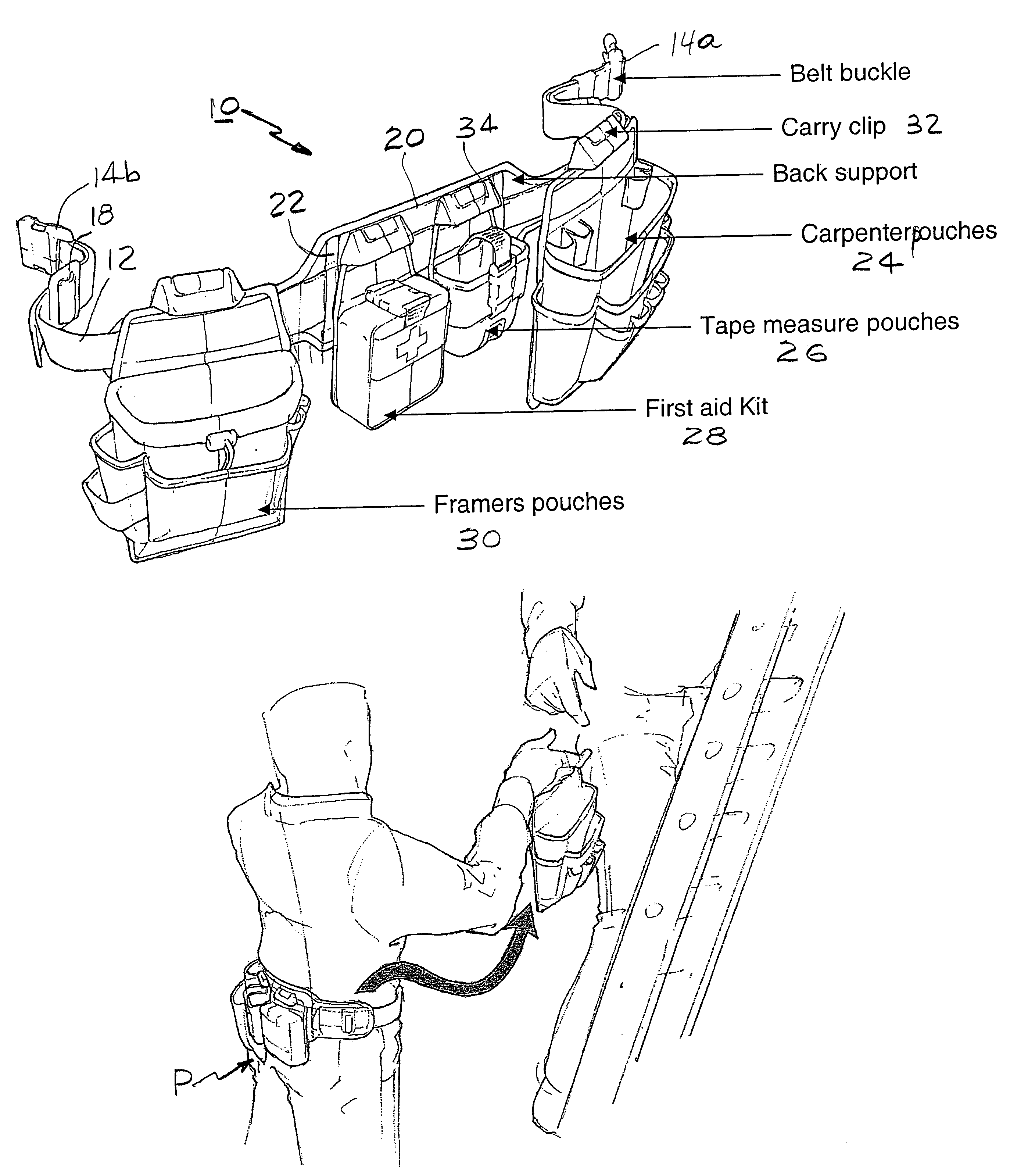
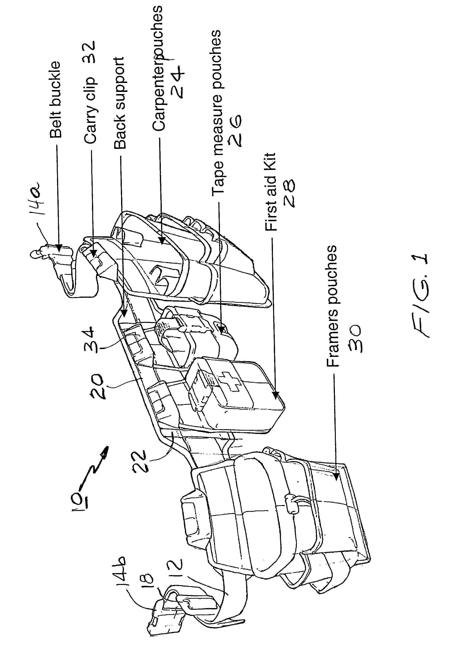
[0029]Referring now to the Figures, in which similar or identical parts are identified by the same reference numerals throughout, and first referring to FIG. 1, a belt utility system in accordance with the present invention is generally identified by the reference 10.

[0030]The belt utility system 10 includes a generally flexible flat belt or strap 12 provided with mating male and female buckle members 14a, 14b. An adjustment member 18 may be provided for adjusting the overall length of the strap 12. A wider and stiffer back support member 20 may be attached to provide enhanced back support. The support member 20 may be attached to the strap 12 in any suitable manner: vertical or transverse straps 22 are used in the illustrative embodiment to form loops through which the belt or strap 12 extends. For reasons that will become evident, the back support 20 is arranged so that the belt or strap 12 remains substantially exposed facing outwardly while in the utility belt is worn by a user....


PUM


Abstract

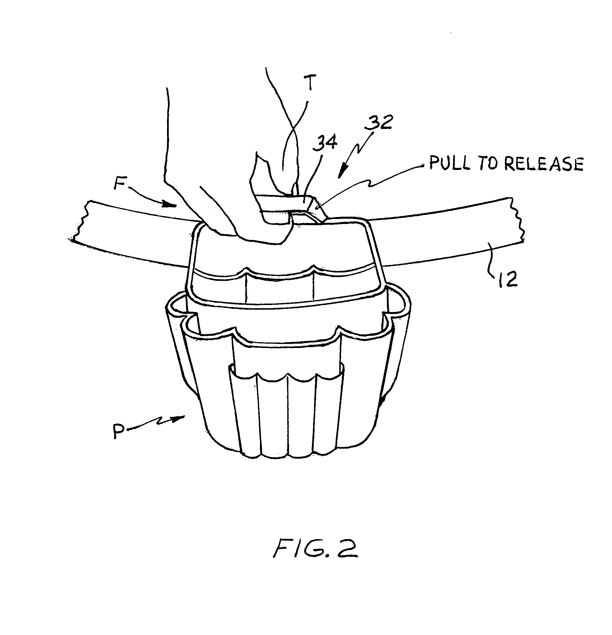
A belt utility system for carrying up to a large number of objects includes an elongated flexible strap for removably supporting a large number of plurality of receptacles or holders for objects, at least one holder or receptacle for an object, as well as a way of removably attaching the receptacle(s) or holder(s) to the strap. This means of attachment includes a finger-gripping portion for facilitating both the simultaneous gripping of holder(s) or receptacle(s) for objects and the detachment, by the user, by generally lifting with the fingers, of these holder(s) or receptacle(s), in a generally upward direction. The utility system can also include a snap-lock connector connected to the strap and to the receptacle or holder, and a releasing tab or button near or on the gripping portion for releasing the connector portions from each other when pressed by the user's finger substantially at the same time as the user lifts the finger-gripping portion.

Description

BACKGROUND OF THE INVENTION[0001]1. Field of the Invention[0002]The invention generally relates to a utility belt system and, more specifically, to a convenient-to-use ergonomic modular / customizable system.[0003]2. Description of the Prior Art[0004]Tool bags and / or belt-supported pouches for carrying nails, screws, bolts and other tools are well-known in the industry. Typically, a “tool belt” is a belt having a number of pouches and / or tool holders fixedly or permanently attached to the belt. However, since no two people are alike or perform their tasks in exactly the same way, the preferred locations, sizes and shapes of the pouches and tool holders varies according to the person and the task at hand. Accordingly, there is a need for a tool belt that can be easily modified to suit the individual and the specific task.[0005]Numerous tool bags and tool belts have been proposed that have removable or interchangeable pouches or tool holders. However, these tool bags offer only a limite...

Claims


Application Information

Patent Timeline
Patent Type & Authority Patents(United States)
IPC IPC(8): A45F3/04A45F5/00A45C1/04A45F5/02F41C33/02F42B39/02
CPCA45F5/02A45F5/021A45F5/00A45F2200/0575A45F2003/144A45F2005/026
Inventor PANOSIAN, MICHAELKANG, PAOLOKEELER, JOSHUA M.STOBAR, JAMES KENDALL
Owner PANOSIAN MICHAEL
Learn More