

Variability-aware scheme for asynchronous circuit initialization
a technology of asynchronous circuit and variable scheme, applied in the field of asynchronous logic circuit, can solve the problems of not being able to store different data, and none of the previous proposals disclosed techniques adequate for a provably correct and fully automated flow
- Summary
- Abstract
- Description
- Claims
- Application Information
AI Technical Summary
Problems solved by technology
Method used
Image

Examples
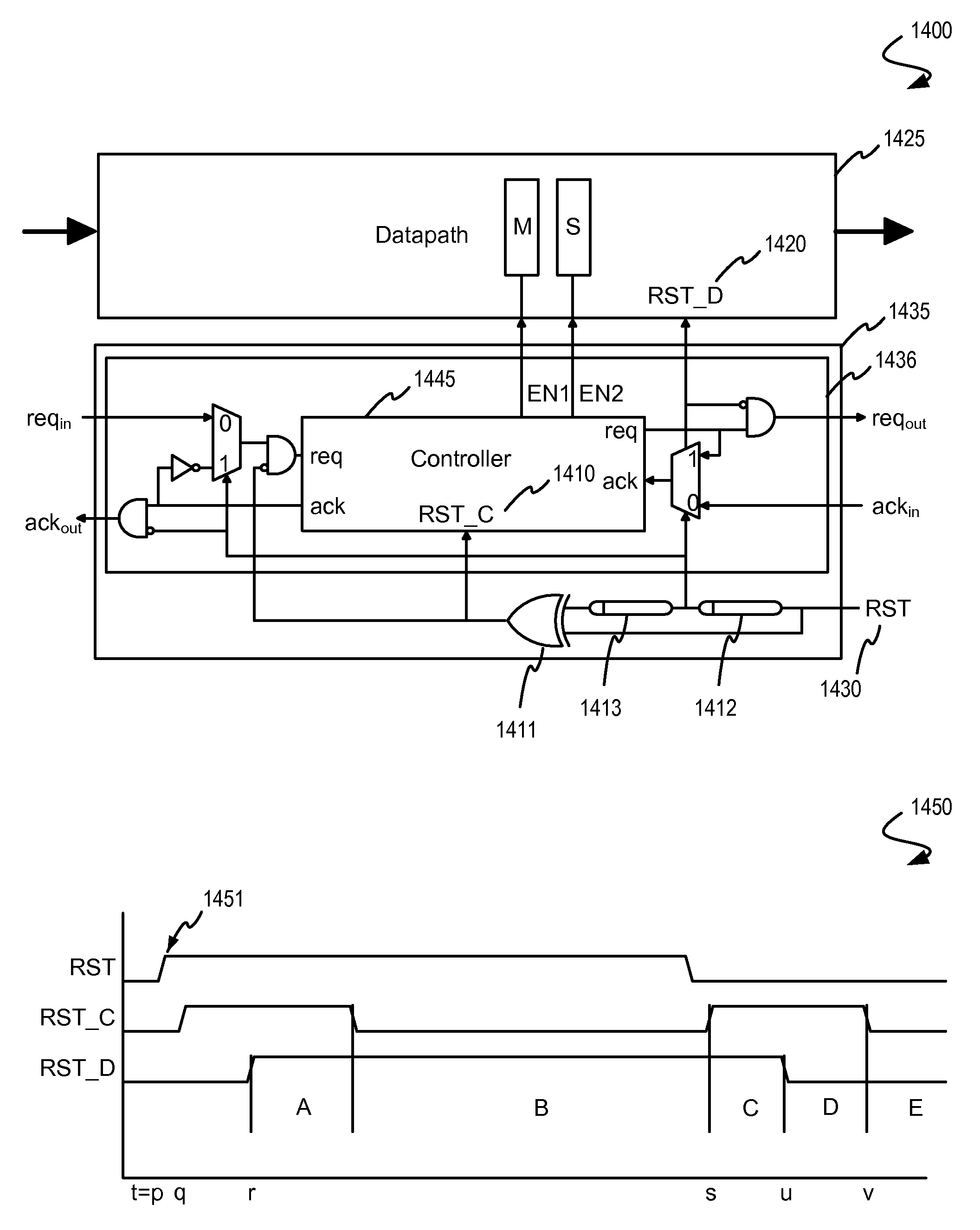
embodiment 1400
[0254]Also, other partitioning of circuits are possible and envisioned. In particular, the blocks of embodiment 1400 are described in the context of resetting circuits in a series of computation pipeline stages, and such a pipeline would be reasonably fabricated in a single semiconductor die, however, computation pipelines might also be embodied across multiple semiconductor die, or embodied across multiple boards, or even embodied across multiple chassis.
Automatic Voltage and Speed Regulation
[0255]Since asynchronous circuits are tolerant to the variability of delays, they can easily incorporate self-control mechanisms that adapt the speed and power supply of the circuit to the dynamic requirements of the environment.
[0256]Certain voltage regulation approaches are based on the dynamic load presented to the computing device. A typical situation where this approach can be applied is in a data-processing circuit that processes data received from queued input data. The processing speed ...
embodiment 1950
[0267]The voltage regulators 1921, 1923 and 1925 can be instanced to each controller independently. In the embodiment shown each regulator 1921, 1923 and 1925 is connected to a common power rail Vdd, and produces a regulated Vdd voltage on a voltage supply rail 1941, 1942, 1943 that in turn powers supply voltage connections to the circuit elements in the data path (which supply connections are not shown in the embodiment 1950).
[0268]The aforementioned descriptions apply to the two-phase controllers described herein. Notwithstanding, one or more of the techniques for regulating voltage to maximize power efficiency in a circuit might be applied in a system implementing a four-phase protocol. Moreover, while the aforementioned techniques disclose voltage regulation of the supply voltage, techniques to change voltage biasing might as well be applied within the context of the embodiments of the invention herein.
[0269]The electronic systems into which various embodiments of the present in...
PUM
 Abstract
Description
Claims
Application Information