
Configurable multi-modulus frequency divider for multi-mode mobile communication devices

a multi-modulus, mobile communication technology, applied in pulse automatic control, pulse technique, climate sustainability, etc., can solve the problems of frequency divider consuming an undesirably large amount of power, frequency divider producing an amount of noise, and consuming an amount of power, so as to achieve less noise, increase the power consumption of a configuration, and reduce the effect of power consumption

Active Publication Date: 2008-05-27
QUALCOMM INC
View PDF11 Cites 15 Cited by
  • Summary
  • Abstract
  • Description
  • Claims
  • Application Information

AI Technical Summary

Benefits of technology

The patent describes a configurable frequency divider in a mobile communication device that can be used in different communication standards to achieve the required noise levels. The frequency divider includes a prescaler and a plurality of modulus divider stages that can be configured into different modes to achieve the desired performance. The modes involve different combinations of the prescaler and the modulus divider stages, resulting in different levels of noise and power consumption. The patent also describes a method for selecting the appropriate mode based on the desired performance requirements of the communication standard. The technical effect of this patent is to provide a flexible and efficient way to achieve the required noise levels in a mobile communication device while optimizing power consumption.

Problems solved by technology

Due to the high frequency operation of the frequency divider, the frequency divider may consume an undesirably large amount of power.
In each configuration, the frequency divider produces an amount of noise and consumes an amount of power.
The unused MDS stages are disabled, unpowered, or are otherwise made to consume little or no power.

Method used


Image

  • Configurable multi-modulus frequency divider for multi-mode mobile communication devices
  • Configurable multi-modulus frequency divider for multi-mode mobile communication devices
  • Configurable multi-modulus frequency divider for multi-mode mobile communication devices

Examples


Embodiment Construction

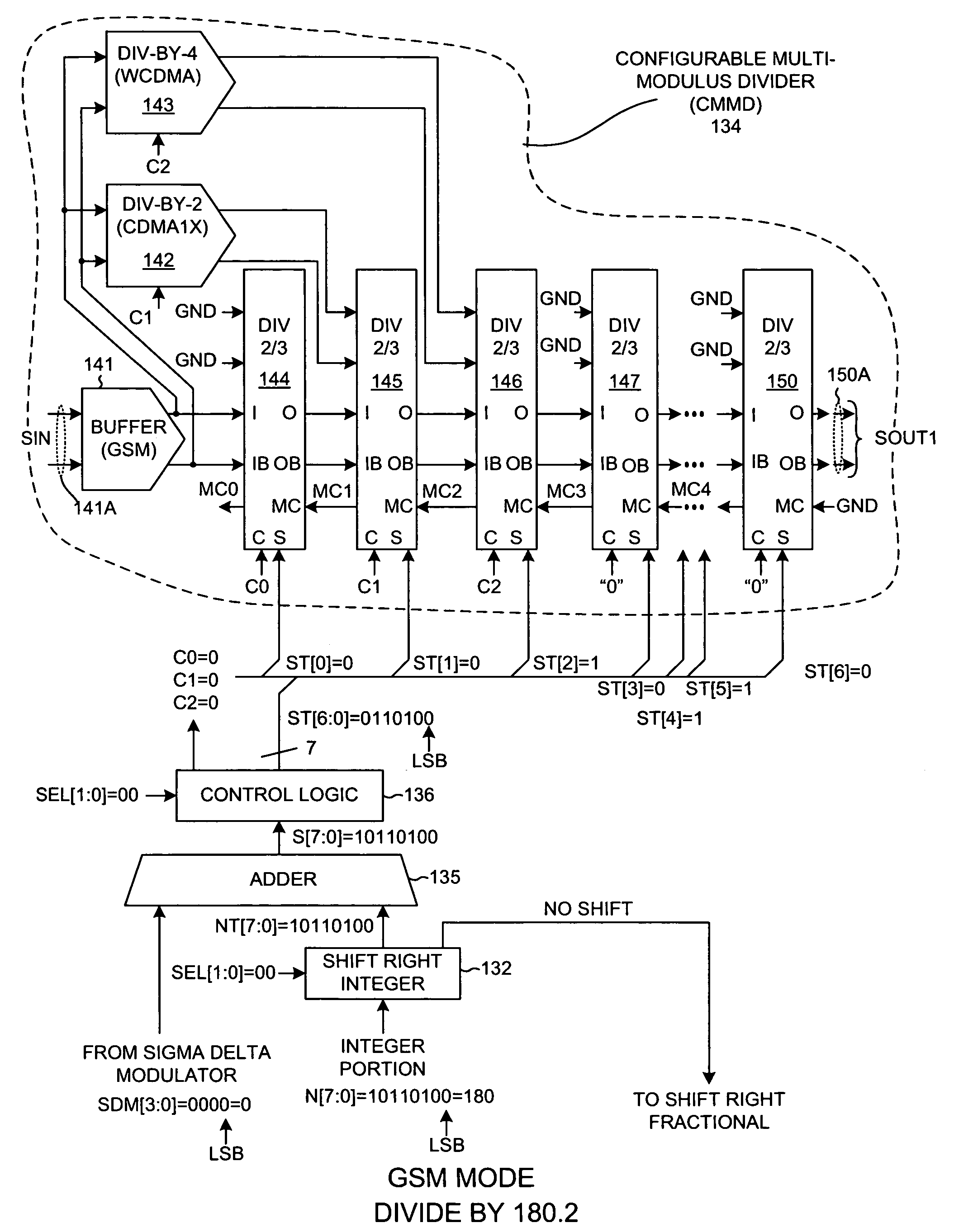
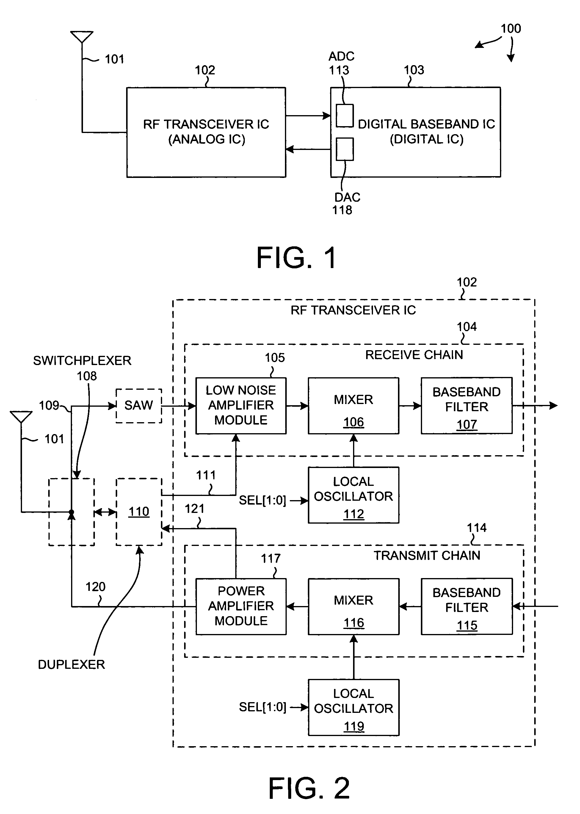
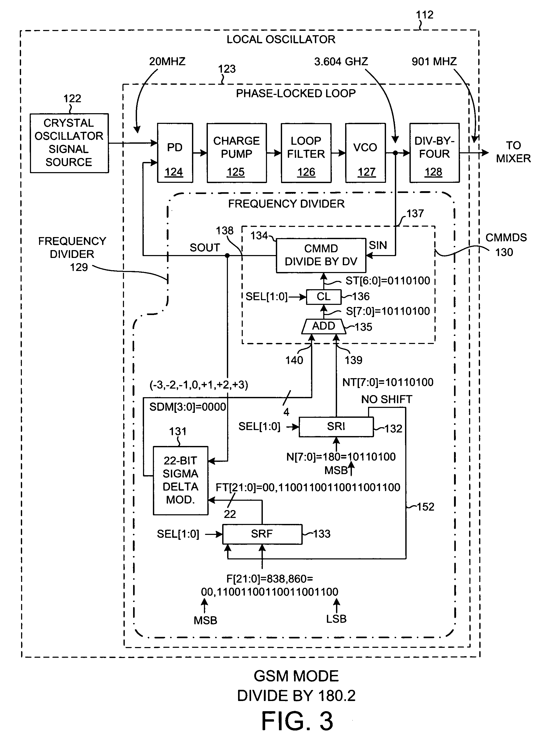
[0035]FIG. 1 is a simplified diagram of a mobile communication device 100 in accordance with one novel aspect. Mobile communication device 100 in this case is a cellular telephone. The cellular telephone is able to communicate using a selectable one of multiple different cellular telephone standards. The cellular telephone can communicate using one standard, and then switch and begin communicating using another standard. Each of the standards places different spurious noise, phase noise and frequency resolution requirements on the local oscillators (LO) in the receiver and transmitter. In the example of FIG. 1, cellular telephone 100 is able to communicate in a selectable one of three cellular telephone standards: GSM (the Global System for Mobile Communications standard, CDMA1X (Code-Division Multiple Access 1X) and WCDMA (Wide-Band Code-Division Multiple Access). Cellular telephone 100 includes an antenna 101 and several integrated circuits including a novel radio frequency (RF) t...


PUM


Abstract

Within a mobile communication device (for example, a cellular telephone), there is a local oscillator. The local oscillator includes a novel frequency divider that includes a novel configurable multi-modulus divider (CMMD). The frequency divider is configurable into a selectable one of multiple configurations involving different mixes of synchronous and asynchronous circuitry. In each configuration, the frequency divider produces an amount of noise and consumes an amount of power. Power consumption is loosely inversely related to noise produced in that the modes with the highest power consumption produce the least amount of noise, and vice versa. The mobile communication device is operable in one of multiple different communication standards (for example, GSM, CDMA1X and WCDMA). The different communication standards impose different noise requirements on the frequency divider. By using the lowest power configuration that satisfies the noise requirements of the standard being used, power consumption of the cellular telephone is reduced.

Description

CROSS-REFERENCE TO RELATED APPLICATION[0001]This application claims the benefit under 35 U.S.C. §119 of Provisional Application Ser. No. 60 / 758,465, filed Jan. 11, 2006, said provisional application is incorporated herein by reference.BACKGROUND INFORMATION[0002]1. Technical Field[0003]The disclosed embodiments relate to local oscillators for use in multi-mode mobile communication devices.[0004]2. Description of Related Art[0005]The receiver and transmitter circuitry within a cellular telephone typically include one or more local oscillators. The function of a local oscillator is to output a signal of a selected frequency. Such a local oscillator in a cellular telephone may, for example, include a phase-locked loop (PLL) that receives a stable but relatively low frequency signal (for example, 20 MHz) from a crystal oscillator and generates the output signal of the selected relatively high frequency (for example, 900 MHz). The feedback loop of the PLL includes a frequency divider tha...

Claims


Application Information

Patent Timeline
Patent Type & Authority Patents(United States)
IPC IPC(8): H03K21/00H03K23/00
CPCH03L7/0802H03L7/1976Y02B60/50H03K21/00H03L7/00
Inventor NARATHONG, CHIEWCHARNSU, WENJUN
Owner QUALCOMM INC
Learn More