
Semiconductor memory chip with on-die termination function

a memory chip and on-die termination technology, applied in the field of semiconductor memory chips, can solve problems such as the synchronous input buffer might malfunction

Active Publication Date: 2010-03-30
LONGITUDE LICENSING LTD
View PDF12 Cites 14 Cited by
  • Summary
  • Abstract
  • Description
  • Claims
  • Application Information

AI Technical Summary

Benefits of technology

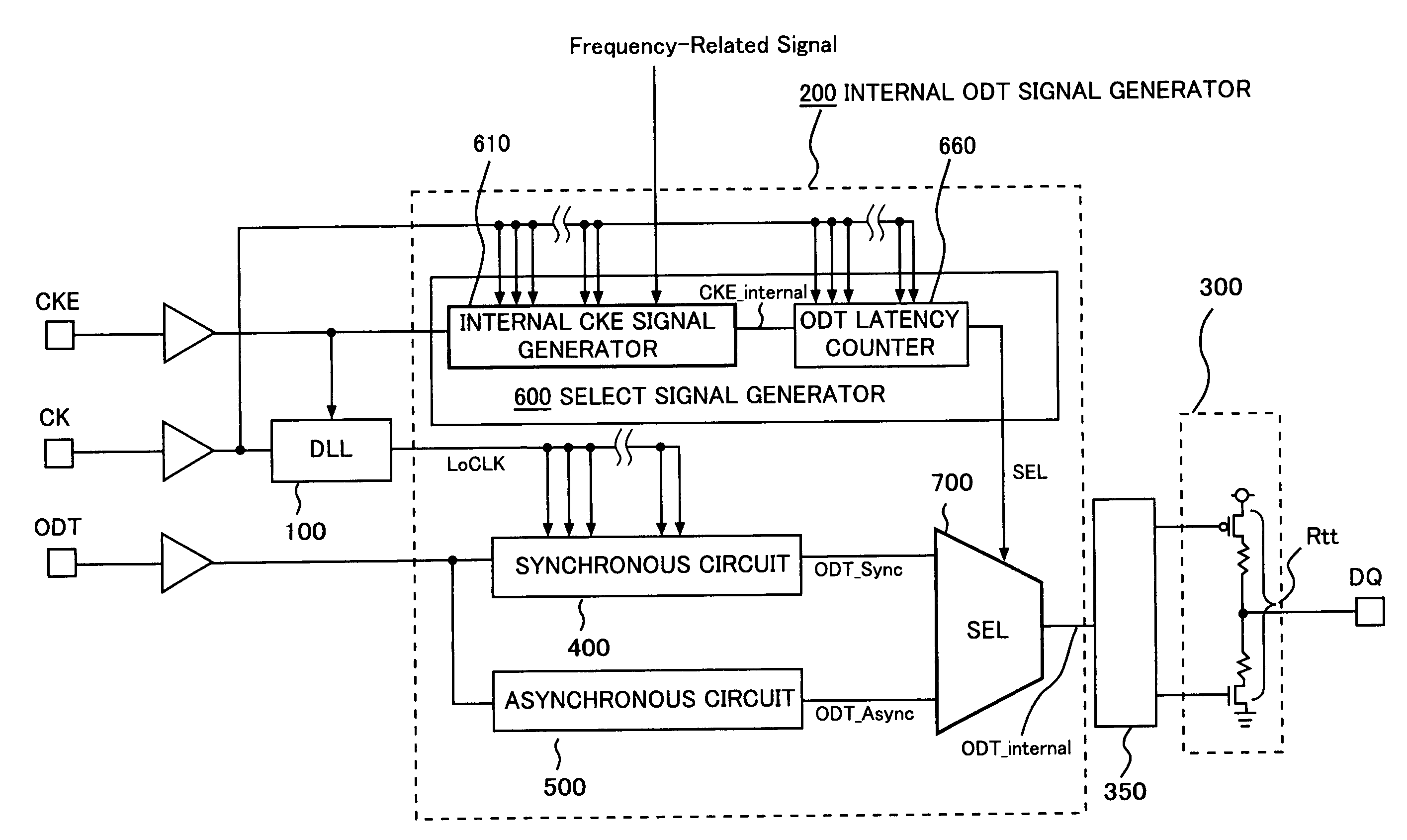
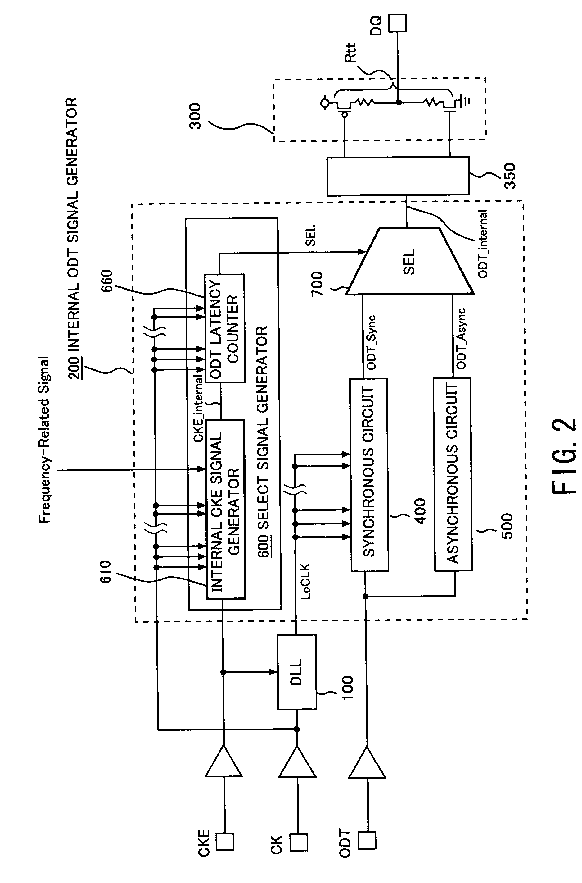
The present invention is related to a semiconductor memory chip with an On-Die Termination (ODT) function. The chip includes a delay locked loop (DLL) circuit, a synchronous circuit, an asynchronous circuit, a select signal generator, and a selector. The DLL circuit produces a local clock signal when a clock enable (CKE) signal is asserted, with a predetermined boost time. The select signal generator asserts a select signal based on the predetermined boost time. The selector selects between the output of the asynchronous circuit and the output of the synchronous circuit, depending on the select signal. The technical effect of this invention is to improve the signal quality and reliability of the semiconductor memory chip by reducing signal delay and improving signal quality.

Problems solved by technology

However, according to the disclosure of EP 1 308 849, there might be raised a problem that the synchronous input buffer might malfunction.

Method used


Image

  • Semiconductor memory chip with on-die termination function
  • Semiconductor memory chip with on-die termination function
  • Semiconductor memory chip with on-die termination function

Examples


first embodiment

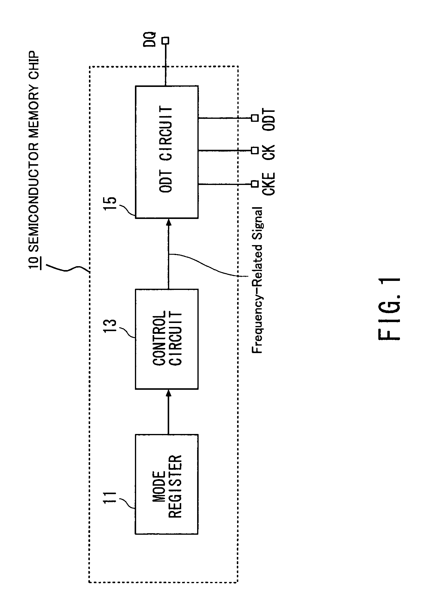
[0014]With reference to FIG. 1, a semiconductor memory chip 10 according to the present invention is a dynamic random access memory (DRAM) chip and comprises a mode register 11, a control circuit 13 and an ODT circuit 15.

[0015]The mode register 11 stores a predetermined value associated with a predetermined frequency at which the semiconductor memory chip 10 is used. For example, the semiconductor memory chip 10 of the present embodiment can be used at four different kinds of predefined frequencies, i.e. 400 MHz, 533 MHz, 667 MHZ, 800 MHz. The predetermined frequency is an actually-used one of the predefined frequencies. The mode register may include an extended mode register.

[0016]The control circuit 13 produces a frequency-related signal on the basis of the predetermined value stored in the mode register 11. The frequency-related signal implies the predetermined frequency. In other words, the frequency-related signal is for notifying which is the predetermined frequency among the ...

second embodiment

[0036]With reference to FIG. 6, the delayed signal generator 645 included in the delay circuit 635 comprises a plurality of delay elements 6461 to 6463 connected in series and a plurality of taps 647. Each tap 647 is connected to one of output portions of the delay elements 6461 and 6462. The delay elements 6461, 6462, 6463 provide delay periods d1, d2−d1, and d3−(d1+d2), respectively. The taps 647 and the output portion 648 of the last stage of the delay element 6463 output the delayed signals 10 tCK+d1, 10 tCK+d2, and 10 tCK+d3, respectively. The differences d1, d2, d3 relative to 10 tCK are determined in consideration of the operation frequency of 533 MHz, 667 MHz and 800 MHz, respectively.

[0037]Although the frequency-related signal is produced on the basis of the predetermined value stored in the mode register 11 in the above-described embodiments, the frequency-related signal may be directly supplied from the outside of the semiconductor memory chip or may be produced inside o...


PUM


Abstract

A semiconductor memory chip with an On-Die Termination (ODT) function is disclosed, which comprises a delay locked loop (DLL) circuit, a synchronous circuit, an asynchronous circuit, a select signal generator, and a selector. The DLL circuit is configured to produce a local clock signal in response to a clock signal when a clock enable (CKE) signal is asserted. The DLL circuit has a predetermined boost time. The select signal generator is configured to assert a select signal in consideration of the predetermined boost time. The selector is configured to select an output of the asynchronous circuit until the select signal is asserted but to select another output of the synchronous circuit after the select signal is asserted.

Description

BACKGROUND OF THE INVENTION[0001]This invention relates to a semiconductor memory chip such as a dynamic random access memory (DRAM) chip and, in particular, to a semiconductor memory chip with On-Die Termination (ODT) function.[0002]A termination circuit is required for good signal integrity at a high frequency operation, as described in U.S. Pat. No. 7,102,200 B2, which is incorporated herein by reference.[0003]As a relevant technique, EP 1 308 849 A2 discloses a memory circuit with an active termination circuit, which is incorporated herein by reference in its entirety. The disclosed circuit comprises a signal terminal, a synchronous input buffer, an asynchronous input buffer and a switching circuit. The synchronous input buffer has an input coupled to the signal terminal. The asynchronous input buffer has another input coupled to the signal terminal. The switching circuit selectively outputs an output of the synchronous input buffer or another output of the asynchronous input bu...

Claims


Application Information

Patent Timeline
Patent Type & Authority Patents(United States)
IPC IPC(8): G11C8/00G11C5/14
CPCG11C7/1051G11C7/1057G11C7/22G11C7/222G11C7/225H03L7/0812
Inventor HOSOE, YUKIFUJISAWA, HIROKI
Owner LONGITUDE LICENSING LTD
Learn More