
Adaptable phase lock loop transfer function for digital video interface

a technology of digital video interface and transfer function, which is applied in the direction of phase difference detection, automatic control of pulses, electrical devices, etc., can solve the problems of creating jitter patterns, difficult to design a system, and receivers that are compatible (error-free) with all available transmitters

Active Publication Date: 2010-04-20
ANALOG DEVICES INC
View PDF12 Cites 7 Cited by
  • Summary
  • Abstract
  • Description
  • Claims
  • Application Information

AI Technical Summary

Benefits of technology

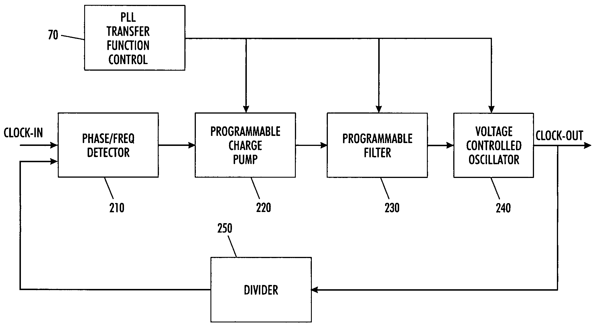
The present invention is a phase-locked loop circuit with an adjustable transfer function. It includes a programmable charge pump, a programmable phase-locked loop filter, a programmable gain voltage controlled oscillator, an integer-N divider, a phase and frequency detector, an error detector, and a transfer function controller. The transfer function controller can change parameters associated with the programmable charge pump, the programmable phase-locked loop filter, or the programmable gain voltage controlled oscillator to adjust the transfer function of the phase-locked loop circuit. The technical effect of this invention is to provide a flexible and programmable phase-locked loop circuit that can easily adjust its transfer function to improve the accuracy and reliability of data transmission.

Problems solved by technology

Although the use of a digital video interface transmitter and a digital video interface receiver reduce electromagnetic interference, there is no standard digital video interface transmitter or digital video interface receiver, thereby creating a multitude of different devices that operate differently from the other.
Due to these variations in the currently available digital video interface transmitters and / or digital video interface receivers, it has become very difficult to design a system, in particular, a receiver that is compatible (error free) with all the available transmitters.
However, there are transmitters that operate at the edge of the standard, possibly falling outside of this bandwidth definition.
Transmitters that operate in these regions often create jitter patterns that a receiver operating within the digital video interface standard cannot track.
When the receiver cannot track the jitter of the data, errors will occur during the data recovery process.
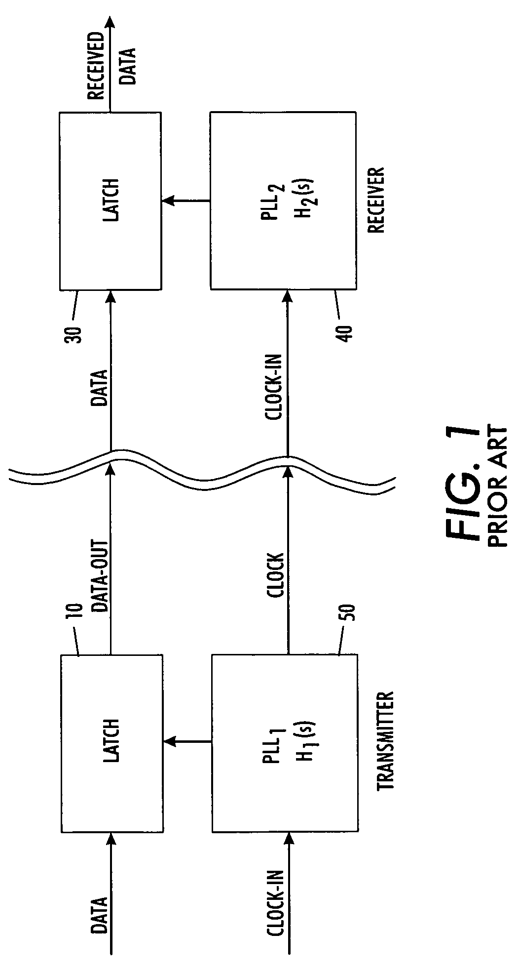
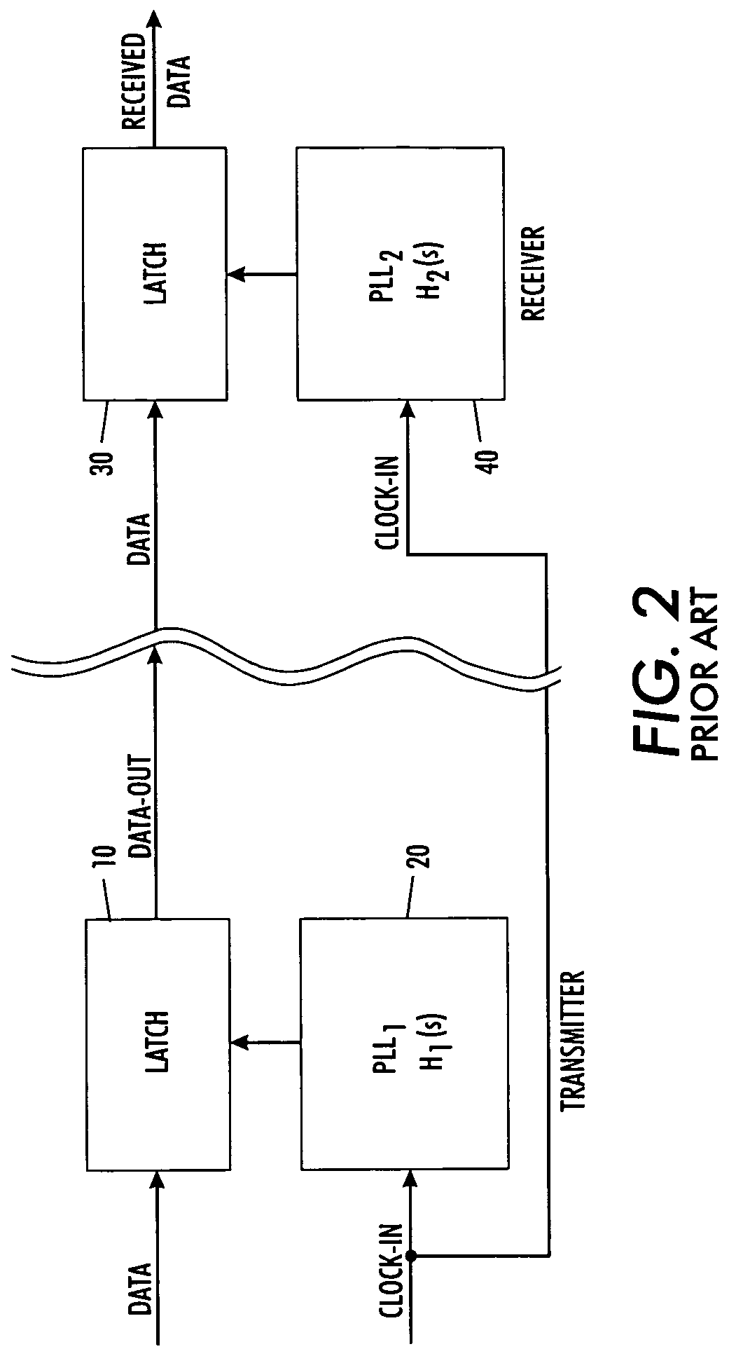
This technique does not ensure that the data and clock signal are synchronous / coherent, causing the data and clock signal to have different jitter patterns and making it more difficult for the conventional digital video interface receiver to acquire the correct data.
The received data will have been processed with this unwanted or unpredictable jitter, but the digital video interface receiver's phase lock loop circuit will be unaware of such a situation due to the absence of this information in the transmitted clock signal prior to it being processed by the digital video interface transmitter's phase lock loop circuit.
Thus, the digital video interface receiver's phase lock loop transfer function will be different from the digital video interface transmitter's phase lock loop transfer function, causing unwanted errors, based upon the differences in transfer functions, and loss of data
However, for certain digital video interface transmitter designs the phase lock loop design is done such to add unwanted jitter to the latched out data.
If the clock that is sent to the digital video interface receiver does not go through the phase lock loop, the jitter pattern of the data cannot be predicted.
However, since different manufactures of digital video interface transmitters will have a different phase lock loop architecture, one phase lock loop design for a digital video interface receiver may not be robust enough to track all digital video interface transmitters.
If the digital video interface receiver's phase lock loop transfer function is different, unwanted errors may occur based upon the differences in transfer functions.
The errors will produce loss of data.

Method used


Image

  • Adaptable phase lock loop transfer function for digital video interface
  • Adaptable phase lock loop transfer function for digital video interface
  • Adaptable phase lock loop transfer function for digital video interface

Examples


Embodiment Construction

[0031]The present invention will be described in connection with preferred embodiments; however, it will be understood that there is no intent to limit the present invention to the embodiments described herein. On the contrary, the intent is to cover all alternatives, modifications, and equivalents as may be included within the spirit and scope of the present invention, as defined by the appended claims.

[0032]For a general understanding of the present invention, reference is made to the drawings. In the drawings, like reference have been used throughout to designate identical or equivalent elements. It is also noted that the various drawings illustrating the present invention are not drawn to scale and that certain regions have been purposely drawn disproportionately so that the features and concepts of the present invention could be properly illustrated.

[0033]As noted above, it is desirable to design a digital video interface receiver that has an adaptable phase lock loop transfer ...


PUM


Abstract

A digital video interface receiver adjusts a transfer function of a phase-locked loop circuit having a programmable charge pump, a programmable phase-locked loop filter, or a programmable gain voltage controlled oscillator. The digital video interface receiver monitors and detects errors in a data stream associated with the phase-locked loop circuit. Moreover, the digital video interface receiver changes the transfer function of the phase-locked loop circuit, in response to the detected errors, by changing parameters associated with the programmable charge pump, the programmable phase-locked loop filter, or the programmable gain voltage controlled oscillator of the phase-locked loop circuit so as to change the transfer function of the phase-locked loop circuit.

Description

FIELD OF THE PRESENT INVENTION[0001]The present invention is generally relates to a receiver for a digital video interface. In particular, the present invention relates to a receiver for a digital video interface having an adaptable phase lock loop transfer function.BACKGROUND OF THE PRESENT INVENTION[0002]A digital video interface is a standard being used for a number of video applications that require high frequency video data transmission from one integrated circuit board to another. The digital video interface standard uses transition minimized differential signals to accomplish this task.[0003]Conventionally, the digital video interface transmitter encodes the data that is sent to a digital video interface receiver to reduce electromagnetic interference. The encoding is done to reduce the occurrence of high frequency transitions that would lead to increased electromagnetic interference levels.[0004]Although the use of a digital video interface transmitter and a digital video in...

Claims


Application Information

Patent Timeline
Patent Type & Authority Patents(United States)
IPC IPC(8): H03D3/24
CPCH03L7/107H03L2207/06H03L7/1072
Inventor MILLER, RODNEY D.STROUD, ERNEST T.HECHT, JR., TEDYIN, JINHJIANGLANIER, TYRE PAUL
Owner ANALOG DEVICES INC
Learn More