Manufacturing test and programming system

a programming system and printed circuit board technology, applied in the direction of testing circuits, instruments, fluid pressure measurement, etc., can solve the problems of difficult to formulate thorough and effective test programs, functional testing suffers from at least two limitations, and the operation is accurate and understandabl

Inactive Publication Date: 2010-04-20
LEANNOUX PROPERTIES
View PDF2 Cites 4 Cited by
  • Summary
  • Abstract
  • Description
  • Claims
  • Application Information

AI Technical Summary

Problems solved by technology

Such functional testing suffers from at least two limitations.
First, it is difficult to formulate thorough and effective test programs suitable for gathering information concerning a variety of circuits designated for test because of the unique nature of individual circuits.
Second, fault isolation to a particular element on a PCB or other circuit assembly having many circuit elements requires an accurate operational understanding of the assembled circuit.
It is difficult to analyze sequential devices.
The complicated nature of the relationships between test signals applied at circuit inputs and the resulting signals at the outputs of the individual sequential device makes it extremely difficult to determine the signals that must be applied at the circuit assembly inputs to “initiate” each sequential device in the circuit assembly.
With the added complexity and density due to miniaturization, it has become more important, and more difficult, to thoroughly test circuit assemblies.
When the embedded circuitry includes programmable devices, the test program can become very complicated and spend an inordinate amount of time managing the programming and test process for a single device.
As a result the in-circuit tester programs are significantly longer and require more resources within the in-circuit tester to execute properly.
The overwhelming nature of this problem caused manufacturers to program all programmable devices on another station prior to the assembly of the PCB or assemble sockets for later insertion of a programmed device.
Solutions to these problems have been long sought but prior developments have not taught or suggested any solutions and, thus, solutions to these problems have long eluded those skilled in the art.

Method used


Image

  • Manufacturing test and programming system
  • Manufacturing test and programming system
  • Manufacturing test and programming system

Examples


Embodiment Construction

[0016]In the following description, numerous specific details are given to provide a thorough understanding of the invention. However, it will be apparent that the invention may be practiced without these specific details. In order to avoid obscuring the present invention, some well-known circuits, system configurations, and process steps are not disclosed in detail.

[0017]Likewise, the drawings showing embodiments of the device are semi-diagrammatic and not to scale and, particularly, some of the dimensions are for the clarity of presentation and are shown greatly exaggerated in the drawing FIGs. Also where multiple embodiments are disclosed and described, having some features in common, for clarity and ease of illustration, description, and comprehension thereof, similar and like features one to another will ordinarily be described with like reference numerals.

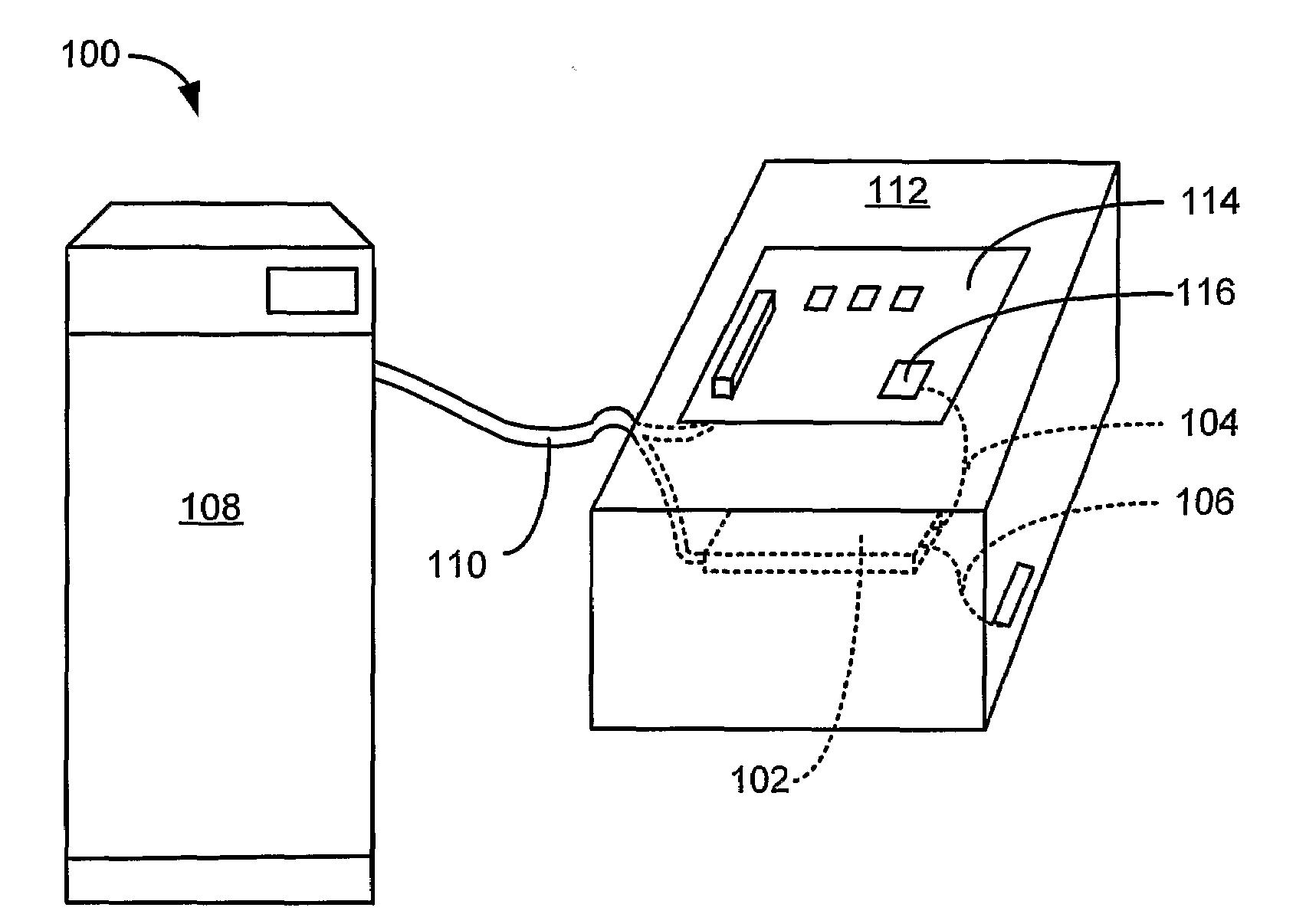
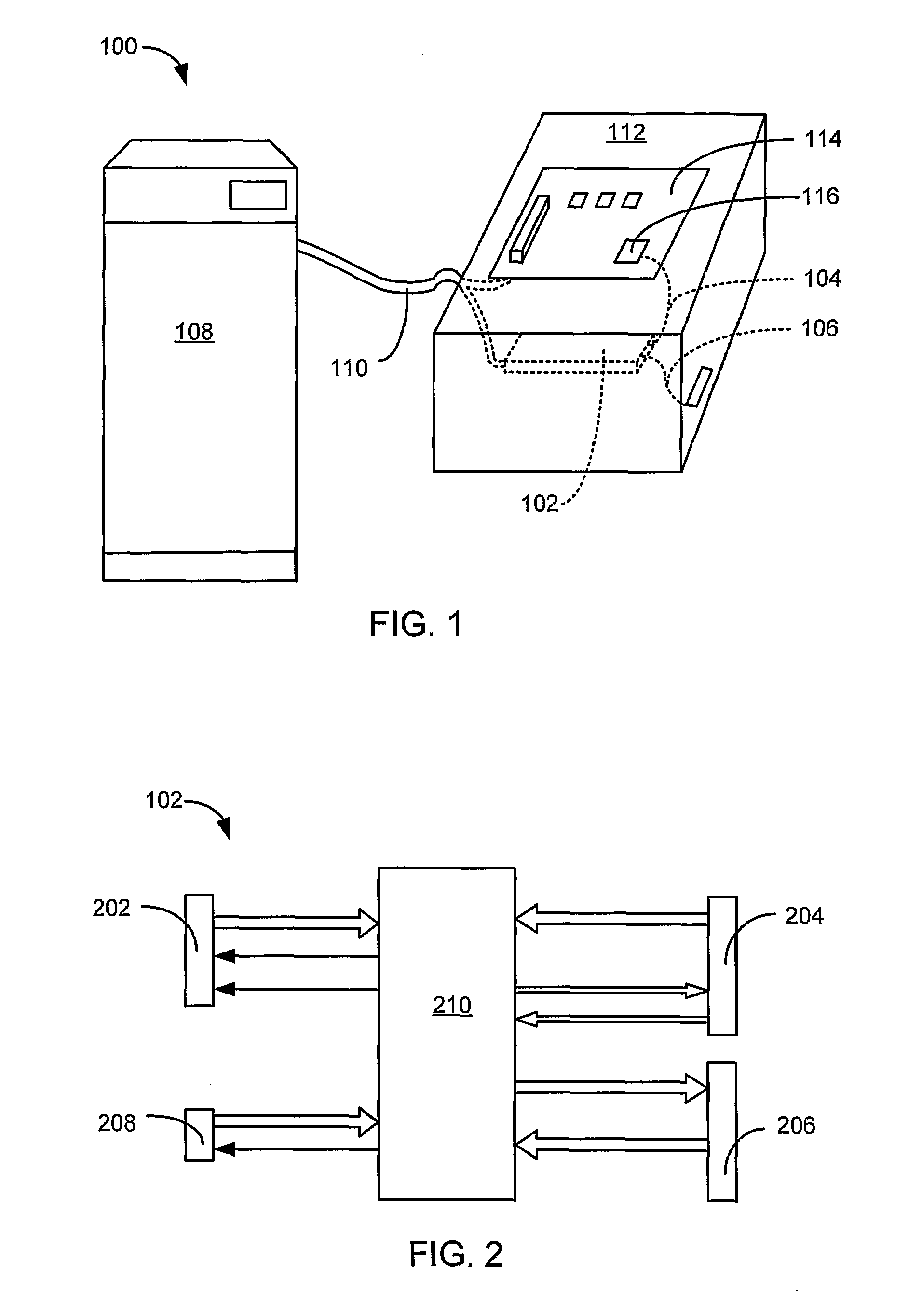
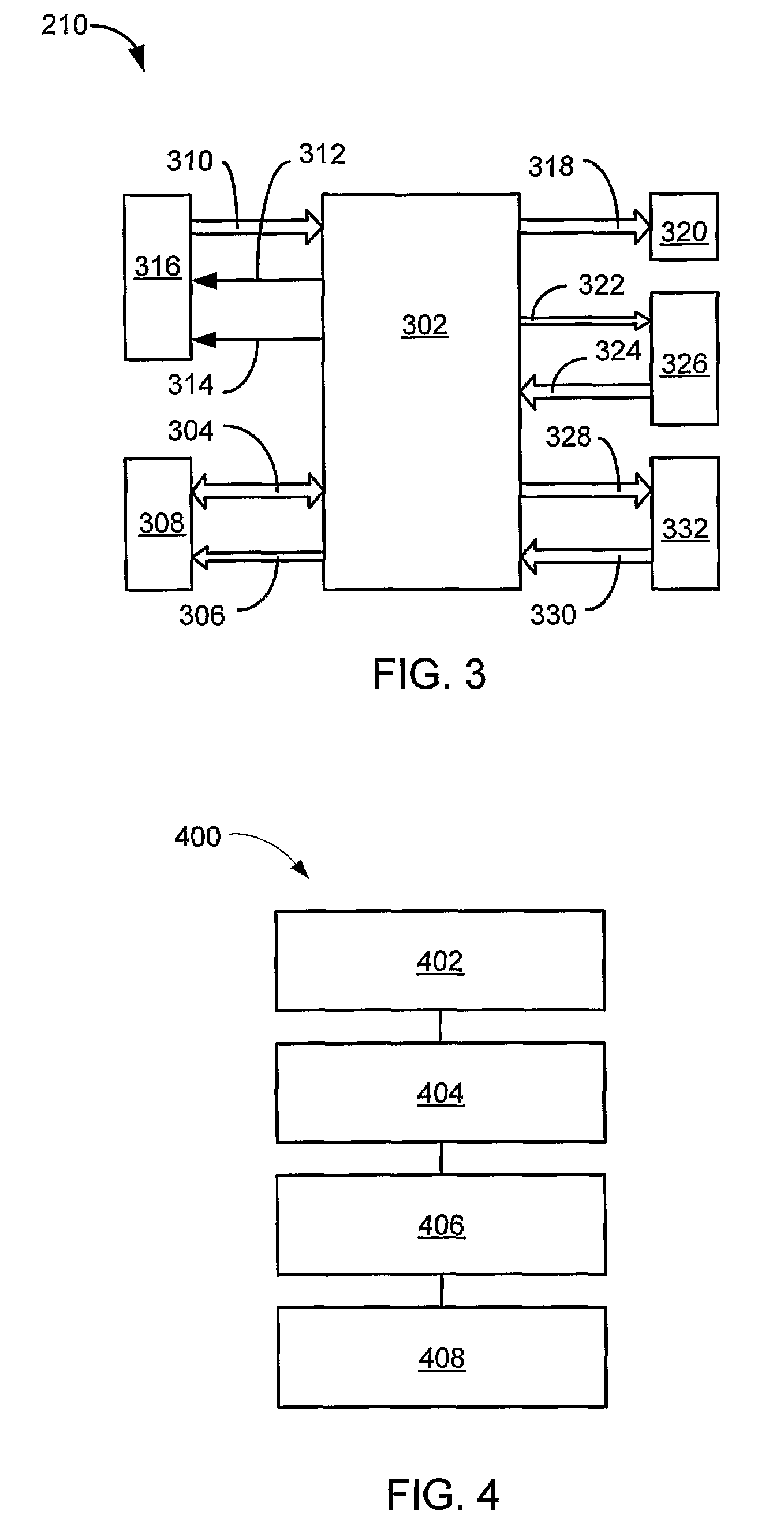
[0018]The term “horizontal” as used herein is defined as a plane parallel to the conventional plane or surface of the devic...


PUM


Abstract

A manufacturing test and programming system (100) is presented including providing a PCB tester (108), providing an in-system programmer (102) electrically attached to the PCB tester (108), mounting a device under test (114) having a programmable device (116) attached thereon and programming the programmable device (116) with the in-system programmer (102).

Description

CROSS-REFERENCE TO RELATED APPLICATION(S)[0001]This application claims the benefit of U.S. Provisional Patent Application Ser. No. 60 / 625,286 filed Nov. 05, 2004 and the subject matter thereof is hereby incorporated herein by reference thereto.TECHNICAL FIELD[0002]The present invention relates generally to printed circuit board test systems, and more particularly to a system for printed circuit board programming and test.BACKGROUND ART[0003]Programmable integrated circuits have applications in all manner of devices. Many of the commodity electronic devices that we take for granted, such as cellular telephones, PDA's, music players and radios, have at least one programmable component among the circuitry on their printed circuit board (PCB). In the manufacturing of millions of these electronic devices yearly, each of the programmable integrated circuits must be programmed and tested with the rest of the components on the board. With high volume manufacturing flow, the interaction with...

Claims


Application Information

Patent Timeline
Patent Type & Authority Patents(United States)
IPC IPC(8): G01R31/00G01M19/00G01M99/00
CPCG01R31/2843G01R31/2806
Inventor BEECHER, DAVID
Owner LEANNOUX PROPERTIES
Why Eureka
Try Eureka