
Polymeric microspheres as degradable fluid loss additives in oilfield applications

a technology of fluid loss additives and polymer microspheres, which is applied in the direction of cabinetry, sealing/packing, and wellbore/well accessories, etc., can solve the problems of premature setting and bridging, undesirable fluid growth, and fracture into a region

Inactive Publication Date: 2010-04-27
SCHLUMBERGER TECH CORP
View PDF66 Cites 17 Cited by
  • Summary
  • Abstract
  • Description
  • Claims
  • Application Information

AI Technical Summary

Benefits of technology

The patent text describes methods and apparatus for creating a fluid for use in a subterranean formation. The fluid can include crosslinked polymer and microspheres that are introduced into the formation to treat it. The microspheres can be crosslinked along their surface and then isolated from the fluid. The technical effect of this patent is to provide a more effective and precise method for treating subterranean formations.

Problems solved by technology

Typically, this is when the fracture is producing unwanted fluids such as water or gas, when there is a non-uniformity of injected fluid, or when expensive materials are being injected into non-producing areas of the formation.
Expensive material loss is a particularly critical reason because the flow of expensive fluid into an already open fracture wastes the material, along with manpower, etc., to produce or increase a fracture where not needed, and in many cases, it results in the growth of a fracture into a region from which undesirable fluid, such as water, is produced.
The disadvantages of cement systems include setting and bridging prematurely.
The hydrating clays are complex to pump, require expensive well work, must hydrate fully along the fracture, and may also bridge prematurely.
Polymer systems have also been attempted for plugging fractures, but often fail due to lack of flow resistance.
Further, use of such systems is expensive because of the requirements for large volumes of materials.
Transportation considerations may also add to the cost of the systems.

Method used


Image

  • Polymeric microspheres as degradable fluid loss additives in oilfield applications
  • Polymeric microspheres as degradable fluid loss additives in oilfield applications
  • Polymeric microspheres as degradable fluid loss additives in oilfield applications

Examples


example 1

[0079]Creation of crosslinked guar microspheres as dissolvable fluid loss additives. To create crosslinked guar microspheres, a two-phase aqueous polymer solution was created containing 2 wt % guar gum and 4 wt % polyethylene glycol (8000 molecular weight) in DI water. Both polymers were added to the water simultaneously while stirring moderately in a WARING BLENDER™. The polymers were continuously stirred for an hour to create a hydrated but phase separating bi-polymer solution. Under shear, the polymer solution consists of guar droplets dispersed in a continuous PEG solution.

[0080]The solution was sheared in this condition while the pH was brought up to approximately 10, and buffered to this condition by the addition of sodium sesquicarbonate. Then, a borate crosslinker solution (in DI water) was added to the sheared polymer blend.

[0081]After shearing for an additional two minutes, the blender was turned off and the contents of the polymer solution were examined. Instead of having...

example 2

[0084]Crosslinked polymer beads with solid acid particles inside. In a second example of making crosslinked polymer beads from guar, the beads of example 1 have been reproduced, but this time with 8 micron particles of polyglycolic acid embedded within the beads. The process is the same as in example 1, but 0.5% by weight of the PGA particles are added to the guar-PEG water-in-water emulsion before the borate crosslinker is added.

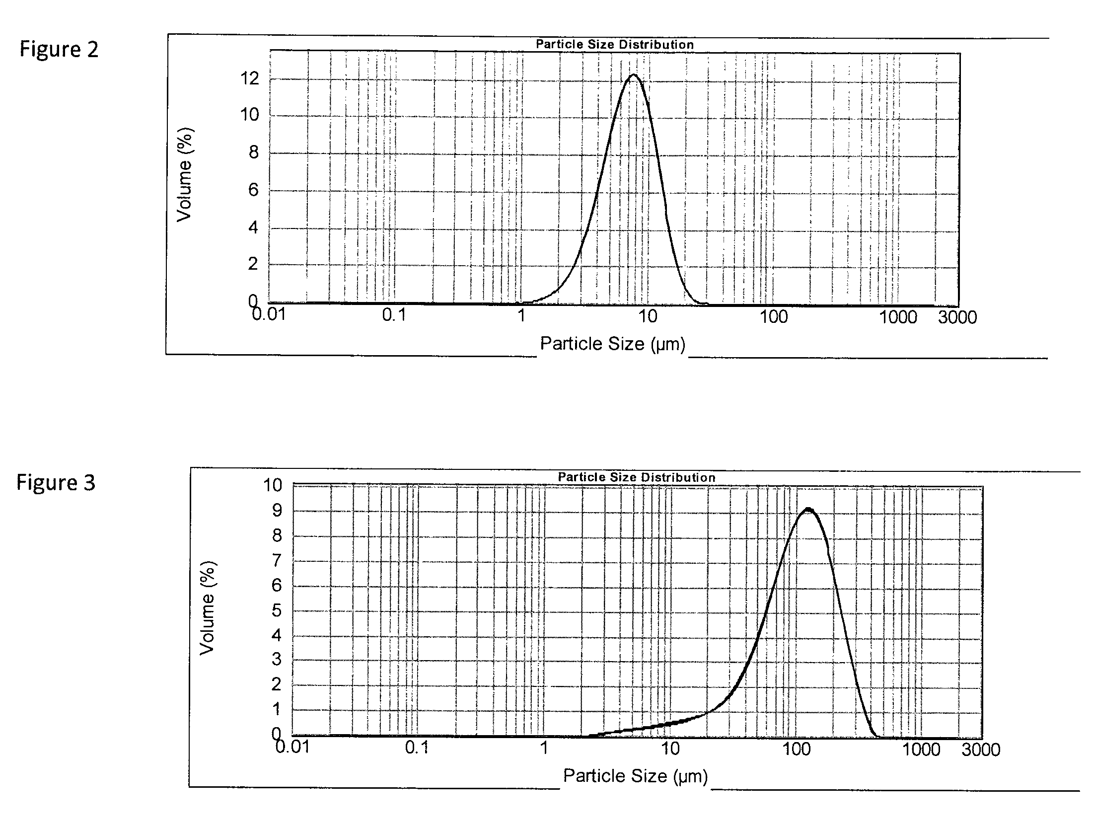
[0085]Care must be taken to assure that the pH remains above 8 during the addition process, as any free glycolic acid must be neutralized when the PGA is added to the mixture. In the example, this was achieved by use of a pH buffer, sodium sesquicarbonate. A picture of the beads embedded with solid acid particles photographed on a microscope slide was taken. The PGA beads are visible as dark spots within the otherwise clear guar beads. The 8 micron PGA particles fit easily in the larger guar beads, and the mean bead size (as measured on the Mastersizer) is ...

example 3

[0087]Crosslinked polymer beads. The previous examples have focused on crosslinked polymeric microbeads made from guar crosslinked with borate. To demonstrate that the approach of phase separating a polymer in a water-water emulsion has broader application for crosslinking microbeads, this example was created by phase separating sodium alginate (an anionic polysaccharide) with polyethylene glycol and then crosslinking the alginate beads with calcium.

[0088]Sodium alginate was phase separated as the internal droplet phase of an aqueous solution by adding 0.5% sodium alginate, 10% KCl and 6% PEG 8000 into 100 ml of DI water in a WARING BLENDER™. After dispersing the polymers and allowing the mixture to stir for a minimum of 30 minutes, 0.3% CaCl2 was added to crosslink the alginate beads. Upon stopping the blender and measuring the size of the beads on the MASTERSIZER™, they were found to have a broad particle size distribution with most of the particles having characteristics sizes be...


PUM

PropertyMeasurementUnit
pHaaaaaaaaaa
diameteraaaaaaaaaa
diameteraaaaaaaaaa

Abstract

Methods and apparatus for forming a fluid for use within in a subterranean formation including crosslinking a polymer along the surface of microspheres in a water-in-water emulsion and introducing the microspheres into the subterranean formation. Methods and apparatus for forming a fluid for use within in a subterranean formation including crosslinking a polymer along the surface of microspheres in a water in water emulsion, isolating the microspheres from the emulsion, and introducing the microspheres into the subterranean formation. Methods and apparatus for forming a fluid to treat a subterranean formation including introducing a crosslinkable polymer, partitioning agent, and crosslinker into a solvent, crosslinking the crosslinkable polymer, isolating beads of the crosslinkable polymer from the partitioning agent, introducing the beads into a fluid for treating a subterranean formation.

Description

CROSS REFERENCE TO RELATED APPLICATIONS[0001]This application claims priority to and the benefit as a continuation in part application of U.S. patent application Ser. No. 12 / 033,630, filed Feb. 19, 2008, which is incorporated by reference herein in its entirety.FIELD OF THE INVENTION[0002]The invention relates to fluid loss additives for use in oilfield applications for subterranean formations. More particularly, the invention relates to filter cakes, particularly to easily destroyable filter cakes formed from polymeric microspheres.BACKGROUND OF THE INVENTION[0003]The statements in this section merely provide background information related to the present disclosure and may not constitute prior art.[0004]Fractures in oilfield reservoirs typically have the highest flow capacity of any portion of the reservoir formation. In natural fractures, the high flow capacity results when the fracture is open and the closure stress is low. In artificially created fractures, the high flow capacit...

Claims


Application Information

Patent Timeline
Patent Type & Authority Patents(United States)
IPC IPC(8): E21B33/13E21B43/267
CPCC09K8/512C09K8/887C09K8/685C09K8/516
Inventor SULLIVAN, PHILIP F.TUSTIN, GARY JOHNWILLIAMSON, DONLADVA, HEMANT K.
Owner SCHLUMBERGER TECH CORP
Learn More