Optical power modulation at high frequency

a technology pulsed light source, which is applied in the field of optical power modulation for high frequency pulsed light source, can solve the problems of spectral range, defy conventional solutions, and exceed the range of modulator devices, and achieve the effect of high frequency pulsed laser modulation

Inactive Publication Date: 2010-04-27
CORNING INC
View PDF24 Cites 1 Cited by
  • Summary
  • Abstract
  • Description
  • Claims
  • Application Information

AI Technical Summary

Benefits of technology

[0018]It is an advantage of the present invention that it allows high frequency pulsed laser modulation in the deep UV region used for lithography.

Problems solved by technology

Each type of modulator that is conventionally used for pulsed laser modulation has some limitations.
However, modulation of a pulsed laser beam in this range presents a number of problems that defy conventional solutions.
One problem relates to the spectral range, which exceeds the range of modulator devices such as AOM and EOM devices.
Another problem relates to high pulse rates.
Thus, the combination of very short wavelengths and relatively high pulse frequencies defies conventional light modulation solutions.
Conventional approaches to pulsed laser modulation, constrained with respect to speed and flexibility, in turn limit the capabilities of UV lithography technology.
However, this type of direct modulation of the laser drive current would only be suitable for pulsed lasers only at speeds below a few hundred Hz.
For these reasons, this type of approach does not provide a workable mechanism for high-speed pulse modulation.U.S. Pat. No. 4,970,546 entitled “Exposure Control Device” to Suzuki et al. describes the use of a spinning filter wheel that interposes a set of filters in the optical path.
Such a solution can be used to provide modulation for earlier pulsed laser sources at 500 Hz.However, this solution would not be usable with laser sources more recently developed that operate at 5-6 KHz.
Thus, although higher pulsed laser frequencies have been achieved in the past few years, lithography systems utilizing UV pulsed lasers have been unable to harness the additional potential this offers for enhanced exposure accuracy and processing speed.

Method used


Image

  • Optical power modulation at high frequency
  • Optical power modulation at high frequency
  • Optical power modulation at high frequency

Examples


Embodiment Construction

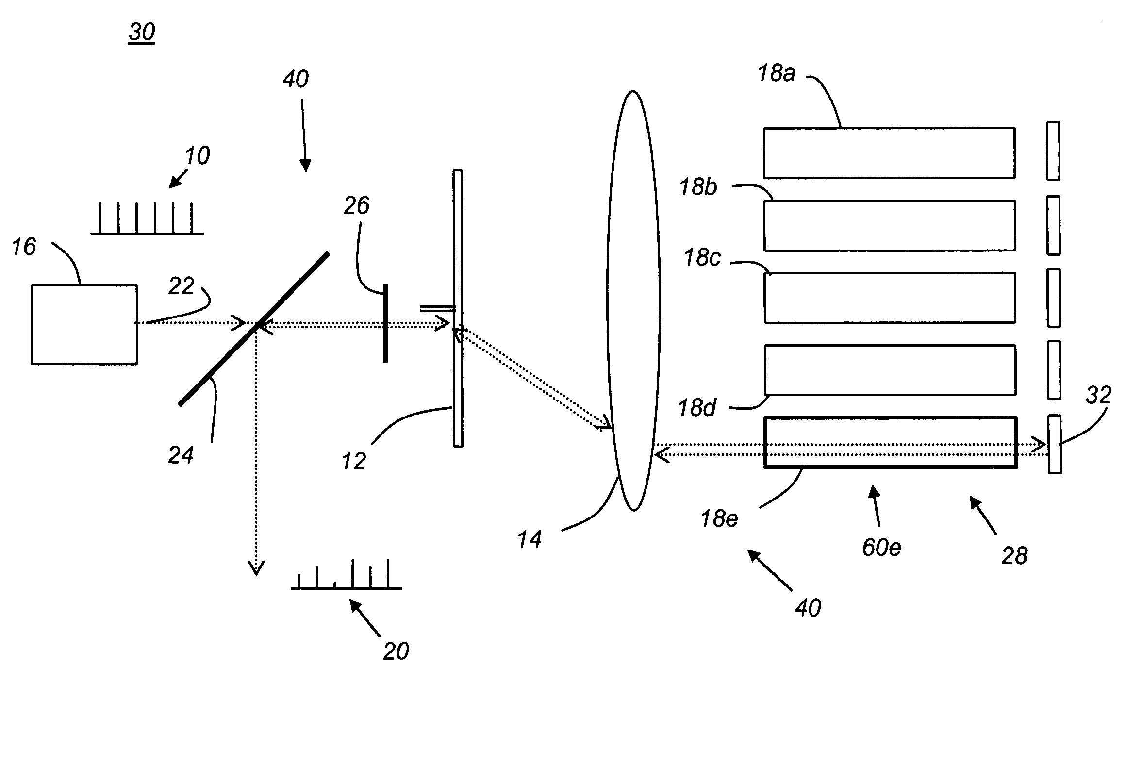
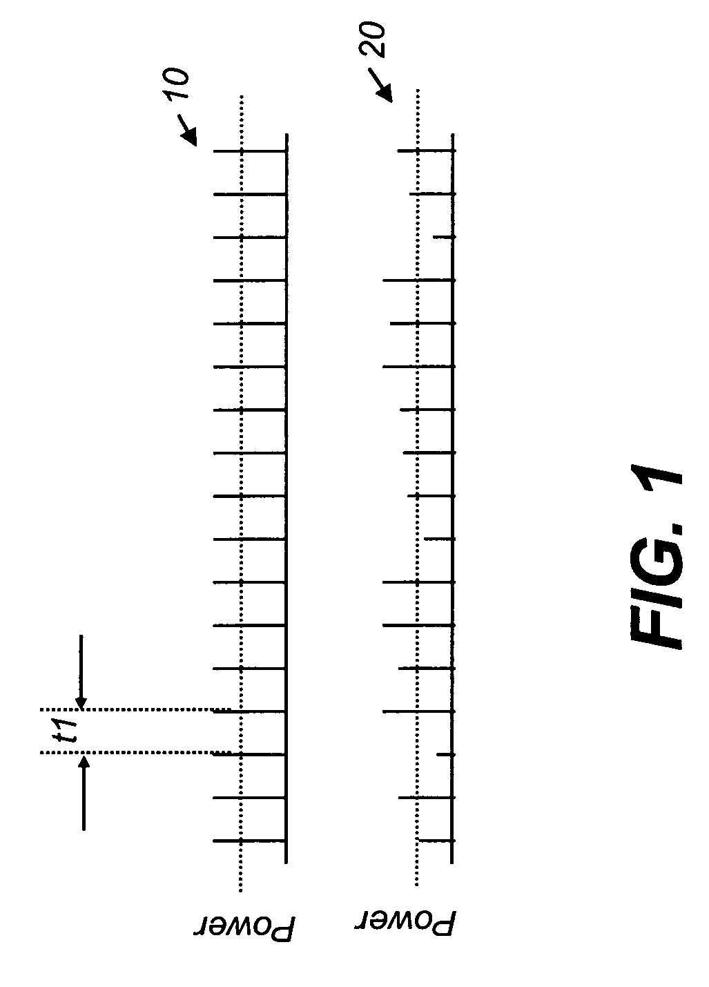
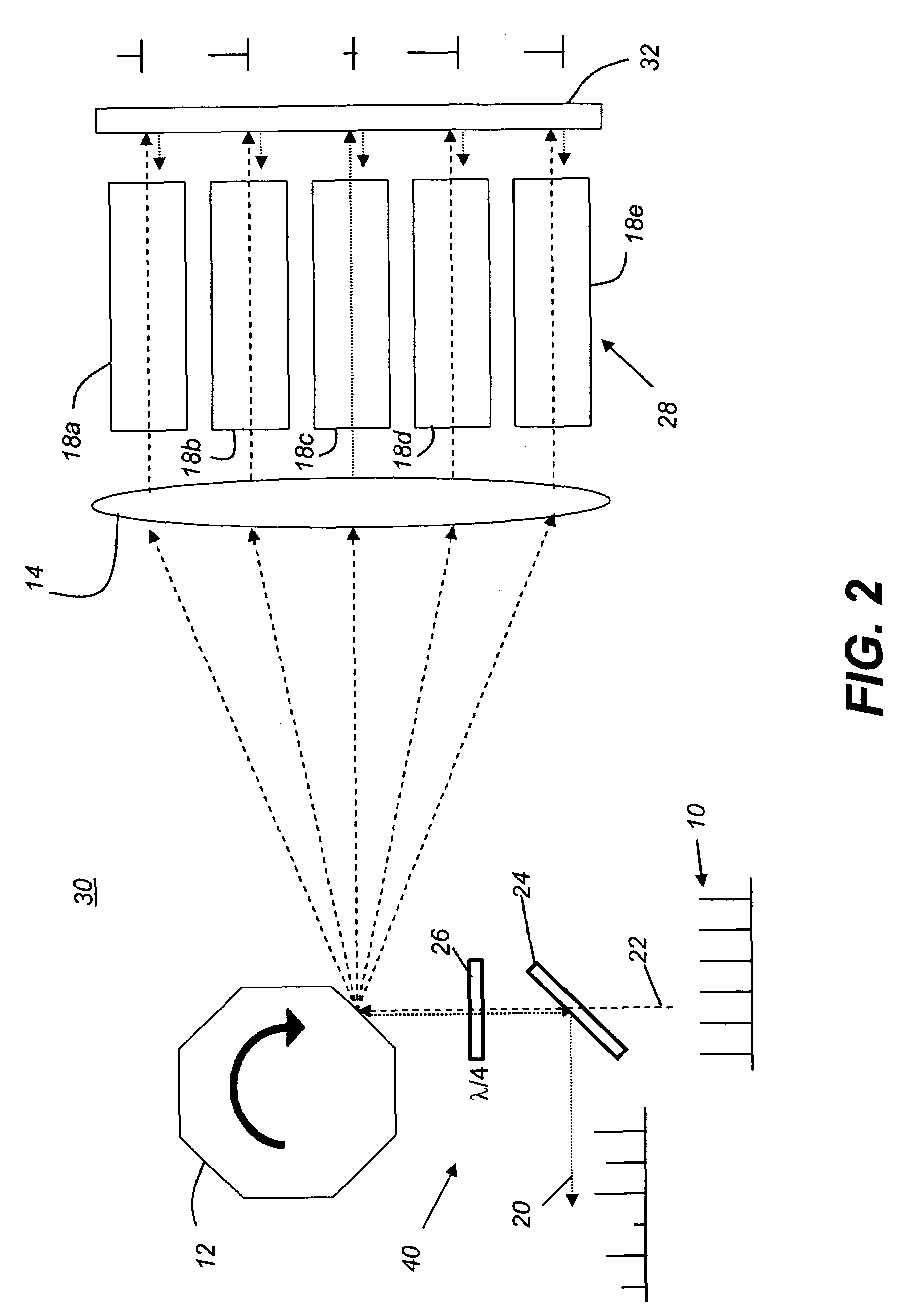
[0032]The timing chart of FIG. 1 shows the overall goal of the present invention: namely, to provide a modulated, high frequency pulsed radiation beam 20 that is generated from a pulsed radiation beam 10 having a relatively constant power output. The apparatus and method of the present invention is adaptable to a range of periods t1, particularly including periods t1 that are shorter than the response times of individual modulating components themselves. In embodiments described subsequently, for example, an array of modulator components, where each individual component has a maximum response time of only about 1 KHz, can be used to modulate a pulsed laser beam at a pulsed repetition frequency of 5 KHz (having a period t1 of 0.2 msec). As FIG. 1 shows, each individual pulse of a high-frequency modulated pulsed radiation beam 20 can be modulated, allowing a highly precise delivery of output power, pulse by pulse. Schematic diagrams in subsequent figures show the path of pulsed radiat...


PUM


Abstract

An apparatus for providing a pulsed radiation beam has a radiation source providing a pulsed radiation beam at a constant pulse repetition frequency. A beam deflector in the path of the pulsed radiation beam is actuable to redirect the pulsed radiation beam cyclically towards each of a plurality of beam intensity modulators in turn. A beam recombiner combines modulated light from each of the plurality of beam intensity modulators in order to form the modulated pulsed radiation beam at the constant pulse repetition frequency.

Description

CROSS-REFERENCE TO RELATED APPLICATIONS[0001]This application claims the benefit of U.S. Provisional Application Ser. No. 60 / 842,306 filed Sep. 5, 2006 entitled “METHOD AND APPARATUS FOR OPTICAL POWER MODULATION AT HIGH FREQUENCY” by Cobb et al.FIELD OF THE INVENTION[0002]This invention generally relates to optical power modulation for high-frequency pulsed light sources and more particularly relates to a method and apparatus for obtaining a pulsed light output with variable power, pulse-to-pulse.BACKGROUND OF THE INVENTION[0003]Pulsed lasers are widely used in applications ranging from surgical devices to lithography systems for forming electronic microcircuits. There are a number of types of devices conventionally used for pulsed laser modulation. These include, for example, devices that deflect a portion of the laser light or cause diffraction, such as various types of acousto-optical modulators (AOM) and electro-optical modulators (EOM). Other types of modulators operate using l...

Claims


Application Information

Patent Timeline
Patent Type & Authority Patents(United States)
IPC IPC(8): H01S3/10
CPCG03F7/70041G03B27/42
Inventor COBB, JOSHUA MONROEDEWA, PAUL G
Owner CORNING INC
Why Eureka
Try Eureka