Systems and methods for protection of audio amplifier circuits

a technology for audio amplifiers and circuits, applied in the direction of electrical transducers, digital transmission, volume compression/expansion, etc., can solve problems such as system detection failure conditions, and achieve the effects of avoiding variability inherent in prior art protection mechanisms, facilitating modification, and minimizing shoot-through curren

Inactive Publication Date: 2010-04-27
INTERSIL INC
View PDF12 Cites 9 Cited by
  • Summary
  • Abstract
  • Description
  • Claims
  • Application Information

AI Technical Summary

Benefits of technology

[0018]The various embodiments of the invention may provide a number of advantages over the prior art. For example, by performing the low-pass filtering of the protection signals in a programmable accumulator, the behavior of the accumulator as a low-pass filter may be easily modified after manufacture. The variability inherent in prior art protection mechanisms can therefore be avoided. Further, because the filtered protection information is provided to a programmable controller, the controller can provide a programmable response to various different failure conditions that may be detected, rather than being limited to a single response (i.e., shutting down the system), as in the prior art. Still further, the implementation of digital protection mechanisms as used in the various embodiments may enable functions such as the automatic calibration of signal delays to minimize shoot-through current and optimize the performance of the amplifier. Still other advantages will be apparent to those of skill in the art of the invention.

Problems solved by technology

This system may detect failure conditions including over-current conditions, over-temperature conditions and shoot-through conditions.

Method used


Image

  • Systems and methods for protection of audio amplifier circuits
  • Systems and methods for protection of audio amplifier circuits
  • Systems and methods for protection of audio amplifier circuits

Examples


Embodiment Construction

[0026]One or more embodiments of the invention are described below. It should be noted that these and any other embodiments described below are exemplary and are intended to be illustrative of the invention rather than limiting.

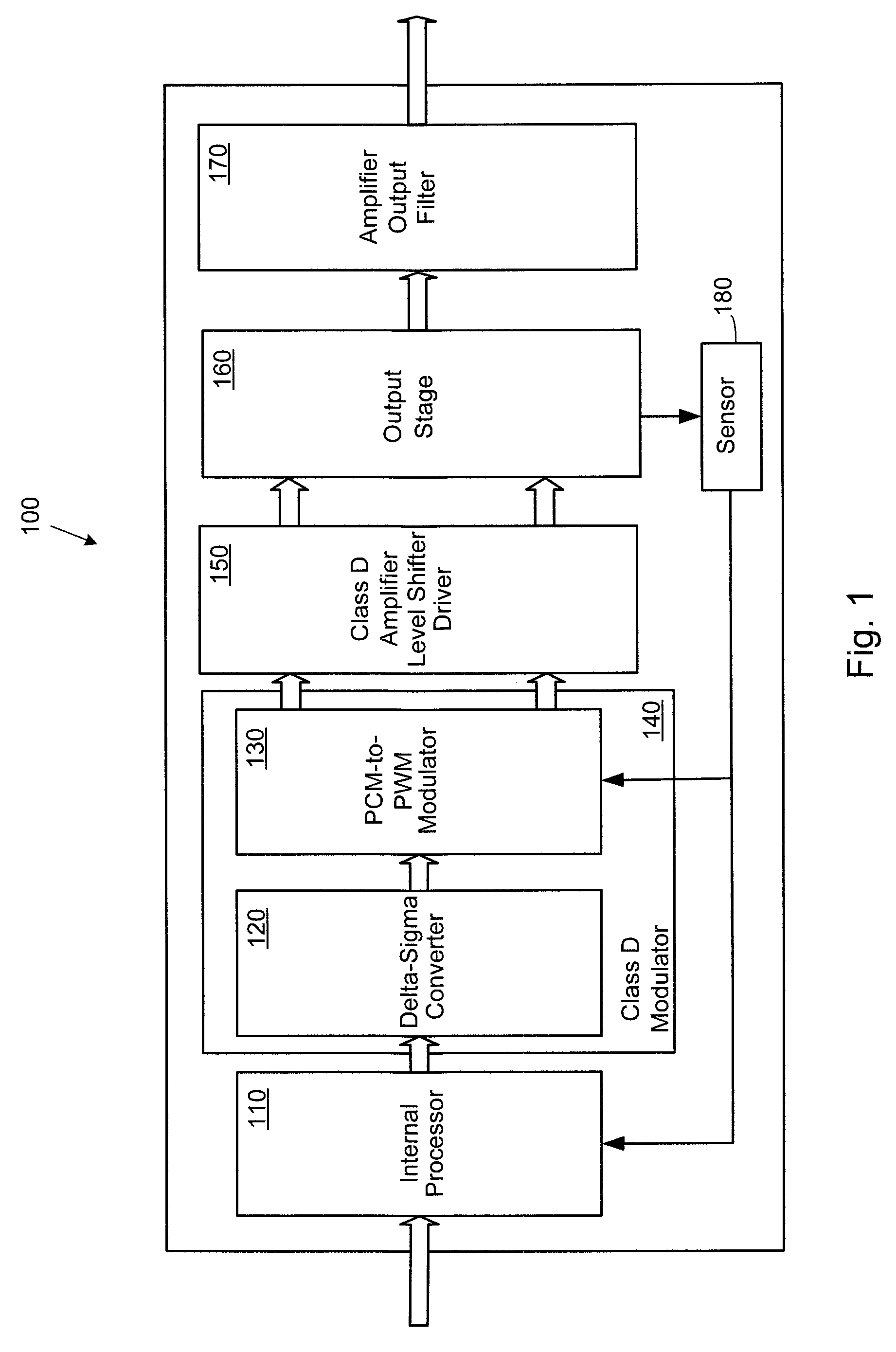
[0027]As described herein, various embodiments of the invention comprise systems and methods for providing protection from failure events in a digital audio amplification system. One embodiment of the invention comprises a protection subsystem for a digital pulse width modulated (PWM) amplification system, wherein signals from failure condition sensors are digitized and low-pass filtered, then processed to determine the appropriate response to the signals. The response to each of the signals and corresponding failure conditions is programmable and may range from no action, to reducing the level of amplification, to shutting down the system.

[0028]In one embodiment, the digital PWM amplification system is implemented using a digital signal processor (DSP) to pr...


PUM


Abstract

Systems and methods for providing protection from failure events in a digital audio amplification system. One embodiment of the invention comprises a system having a digital amplifier controller, an amplifier output stage coupled to the controller and configured to receive audio signals from the controller, one or more sensors coupled to the output stage and one or more low-pass filters coupled to receive sensor signals from the one or more sensors. The low-pass filter is configured to filter the sensor signals and to provide the filtered sensor signals to the controller, which provides a programmable response to the filtered sensor signals. The response may range from not taking any action, to limiting the amplification of audio signals, to shutting down the system.

Description

RELATED APPLICATIONS[0001]This application claims priority to U.S. Provisional Patent Application No. 60 / 469,776, entitled “Marco PWM Protection Logic,” by Kost, et al., filed May 12, 2003; U.S. Provisional Patent Application No. 60 / 456,414, entitled “Adaptive Anti-Clipping Protection,” by Taylor, et al., filed Mar. 21, 2003; U.S. Provisional Patent Application No. 60 / 456,430, entitled “Frequency Response Correction,” by Taylor, et al., filed Mar. 21, 2003; U.S. Provisional Patent Application No. 60 / 456,429, entitled “High-Efficiency, High-Performance Sample Rate Converter,” by Andersen, et al., filed Mar. 21, 2003; U.S. Provisional Patent Application No. 60 / 456,421, entitled “Output Device Switch Timing Correction,” by Taylor, et al., filed Mar. 21, 2003; U.S. Provisional Patent Application No. 60 / 456,422, entitled “Output Filter, Phase / Timing Correction,” by Taylor, et al., filed March 21, 2003; U.S. Provisional Patent Application No. 60 / 456,428, entitled “Output Filter Speaker / Lo...

Claims


Application Information

Patent Timeline
Patent Type & Authority Patents(United States)
IPC IPC(8): H03G11/00H02B1/00H03G7/00H04B15/00H03F1/52H03F3/217H04L7/02
CPCH03F1/523H03F3/2171H04L7/005H03G7/007H04L7/02H03F2200/331H03F2200/351H03F2200/342
Inventor KOST, MICHAEL A.ANDERSEN, JACK B.TAYLOR, WILSON E.
Owner INTERSIL INC
Why Eureka
Try Eureka