Connecting unit for loose ends of a traction device

a technology for connecting units and traction devices, which is applied in the direction of v-belt fastenings, flexible elements, belt fastenings, etc., can solve the problems of only having a single toothed belt. , to achieve the effect of convenient replacement and enhanced connection units

Inactive Publication Date: 2010-05-04
SSI SCHAEFER PEEM
View PDF5 Cites 13 Cited by
  • Summary
  • Abstract
  • Description
  • Claims
  • Application Information

AI Technical Summary

Benefits of technology

[0010]Therefore, it is an object of the present invention to provide an enhanced connecting unit. The connecting unit should be usable particularly for toothed belts, be guidable around return pulleys as well as transmit drive forces by 100%. Further it is desirable that belts, or also single parts of the belt, can be easily replaced.

Problems solved by technology

However, problems arise since welded connections can only transmit 40 to 50% of the force which can be transmitted by belts actually being formed annularly.
However, those are interrupted at welding seam locations.
Another problem exists in that belts, which are actually annular, are only available up to lengths of 24 meters at maximum.
Since an end section of the toothed belt extending over several belts is squeezed, it is no longer possible, after releasing the fastener, to re-close the toothed belt, thus the entire toothed belt becomes useless.
A particular problem is to be seen in that such fasteners occasionally extend in all directions, i.e. fastener elements can be provided in the front, laterally as well as in the back.
Then, guiding the fastener around return pulleys is not possible.

Method used


Image

  • Connecting unit for loose ends of a traction device
  • Connecting unit for loose ends of a traction device
  • Connecting unit for loose ends of a traction device

Examples


Embodiment Construction

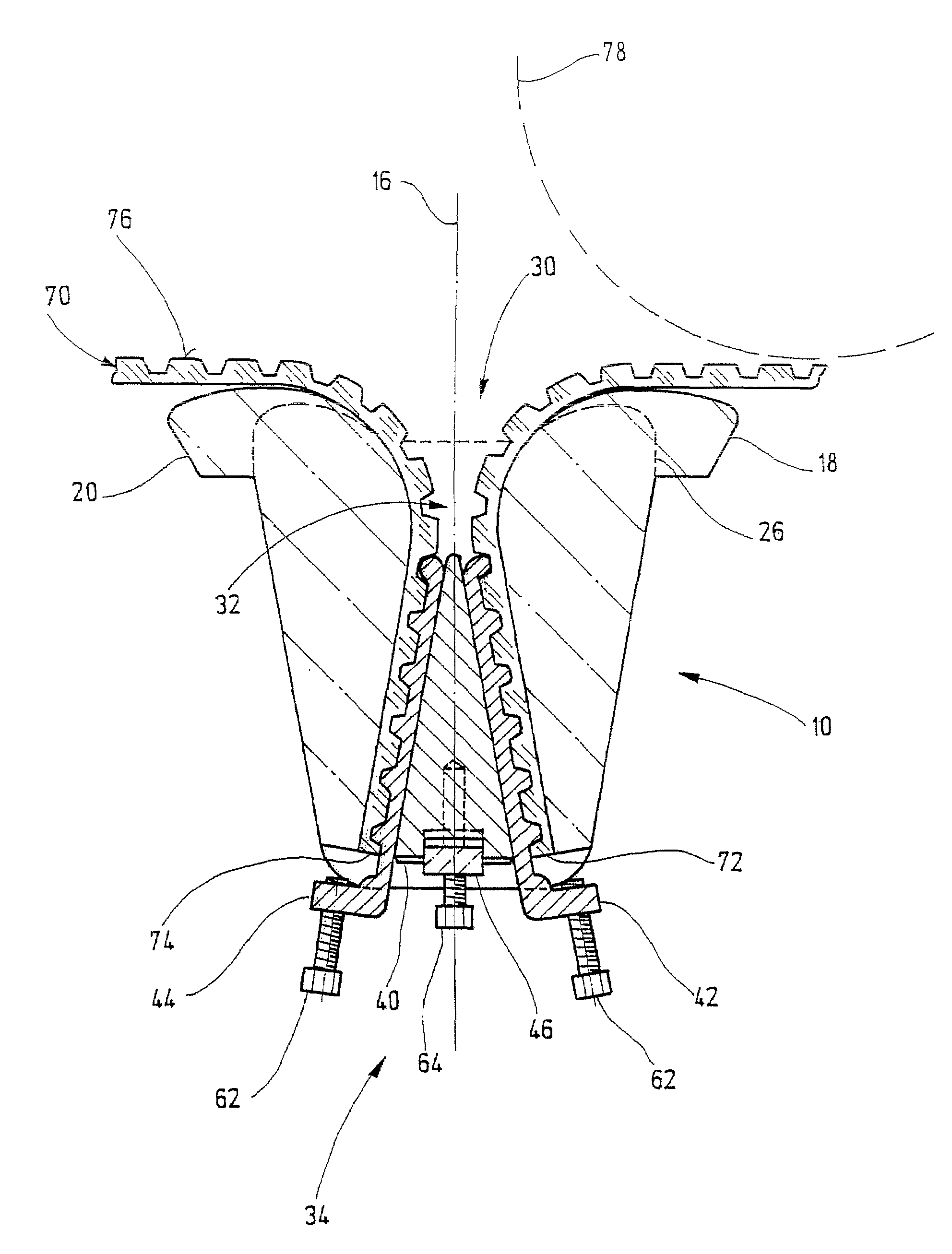
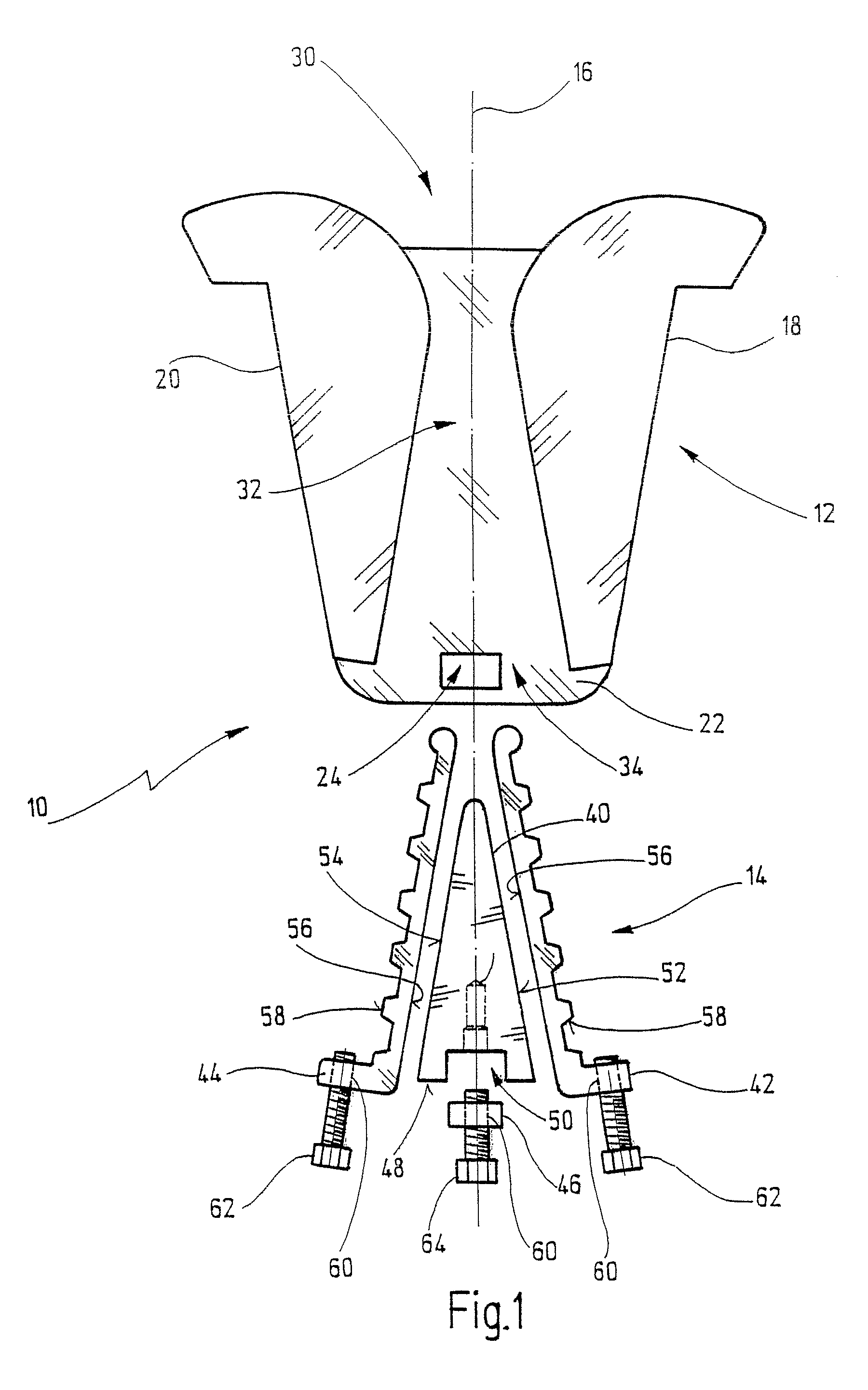
[0049]The connecting unit 10 includes a body 12 and a clamping device 14.

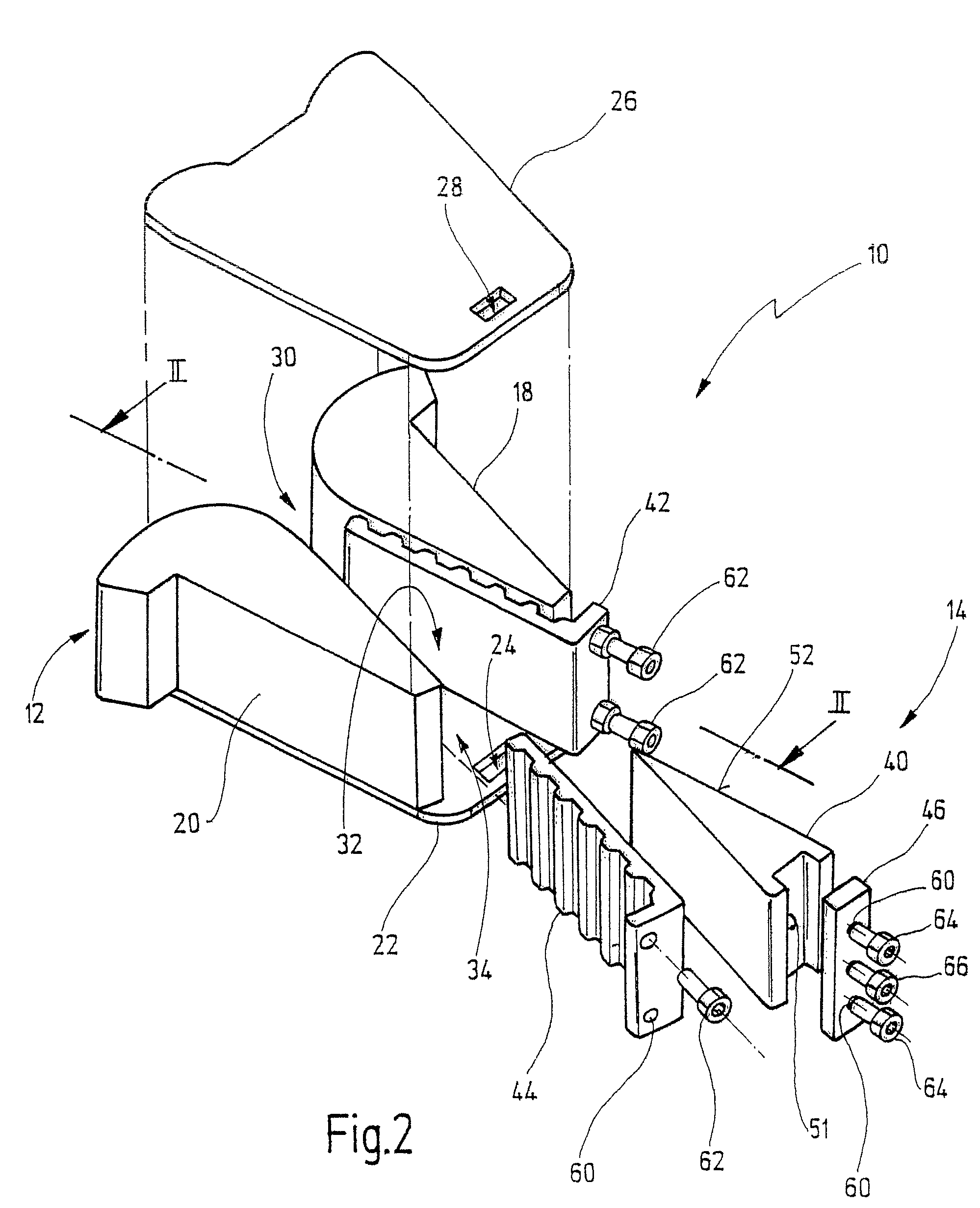
[0050]In FIG. 1 the connecting unit 10 is depicted along its longitudinal axis 16. The body 12 comprises two jaw elements 18 and 20 arranged at left hand side and right hand side of the center axis 16, respectively. The jaw elements 18 and 20 are connected to a ground plate 22. The ground plate 22 has an opening 24, the function of which will be explained in more detail in the following. Additionally, cover plate 26 (not shown in FIG. 1) can be provided, but is not shown in the illustration of FIG. 1 for simplification purposes. This cover plate 26 also has an opening 28 (cf. FIG. 2) arranged opposite to the opening 24 of the ground plate 22 in assembled state of the body 12.

[0051]Both of the jaw elements 18 and 20 have, according to the embodiment shown in FIG. 1, a substantially L-shaped cross section. The short legs of the L-shaped cross section are rounded towards the center axis 16. The roundings define fi...


PUM


Abstract

A connecting unit for loose ends of a traction device includes a body having a traction device passage to receive the ends of the traction device and a clamping device positioned in the traction device passage. The traction device passage has a first opening into which the ends of the traction device can be inserted. The clamping device is adapted to receive the ends of the traction device and has an adjustment mechanism which biases the clamping device in a direction of a wall of the traction device passage.

Description

RELATED APPLICATIONS[0001]This is a continuation application of co-pending international patent application PCT / EP2006 / 007586 (WO 2007 / 014746 A1) which claims priority of the German patent application DE 10 2005 038 446.3, filed on Aug. 3, 2005, which is fully incorporated by reference herewith.BACKGROUND OF THE INVENTION[0002]The present invention relates to a connecting unit for loose ends of traction device.RELATED PRIOR ART[0003]In the field of order-picking technique conveyor lines, such as roller conveyors, are typically driven by one or more motors. For this purpose the motors are connected to elements of the conveyor line to be driven via traction device. As a rule, form-closed traction device, particularly toothed belts and chains are used as traction device. Recently, toothed belts have prevailed due to maintenance reasons. A toothed belt can have the shape of an endless belt, and, for example, can be guided around two deflection pulleys being belt sprockets. The deflectio...

Claims


Application Information

Patent Timeline
Patent Type & Authority Patents(United States)
IPC IPC(8): F16G3/00F16G3/08
CPCF16G3/06Y10T24/16Y10T24/3978
Inventor SCHAEFER, GERHARD
Owner SSI SCHAEFER PEEM
Why Eureka
Try Eureka