Modular transmission system

a transmission system and module technology, applied in the field of modules, can solve the problem of not being able to accommodate a very large range of transmission ratios

Inactive Publication Date: 2010-05-04
SEW-EURODRIVE GMBH & CO KG
View PDF15 Cites 11 Cited by
  • Summary
  • Abstract
  • Description
  • Claims
  • Application Information

AI Technical Summary

Problems solved by technology

In particular, it is also impossible here to accommodate a very large range of transmission ratios.

Method used


Image

  • Modular transmission system
  • Modular transmission system
  • Modular transmission system

Examples


Embodiment Construction

[0020]In the following description, the same reference numerals are used for identical parts or parts with identical actions.

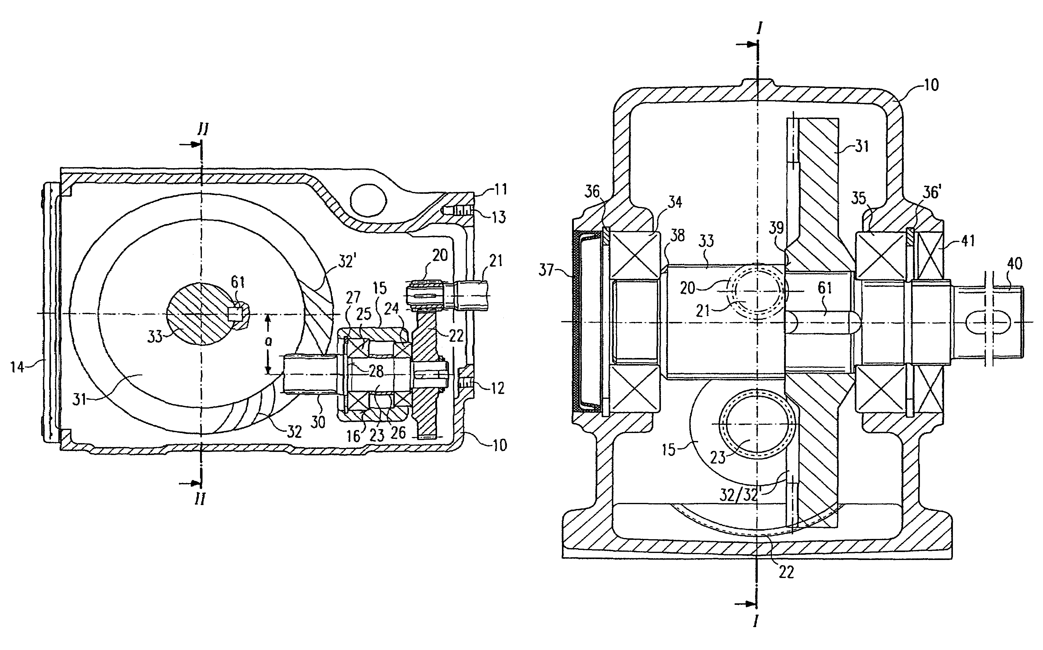
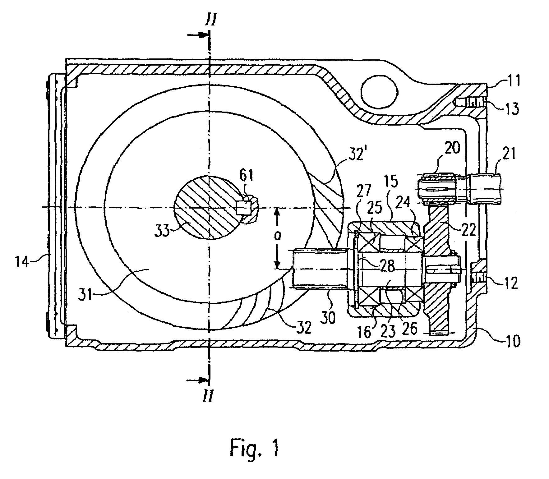
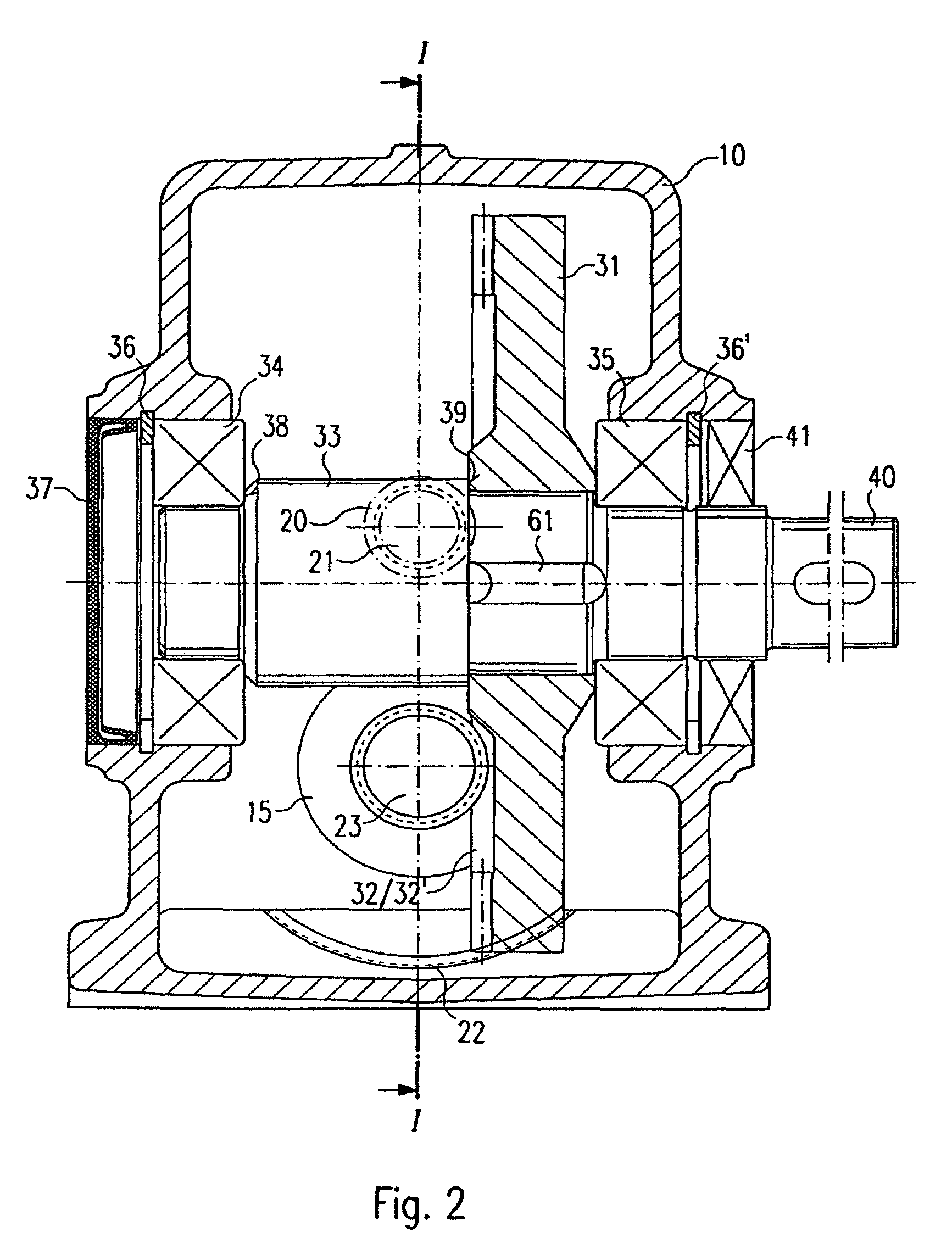
[0021]As can be seen in FIGS. 1 and 2, a housing is provided that comprises on one side a flange 11 for mounting an electric motor (not shown here), for the attachment of which bores 12, 13 are provided in the housing 10. To make the interior of the housing accessible a cover 14 is provided, which is fixed firmly to the housing 10 by means of threaded bolts (not shown) and sealing devices. When a motor has been mounted on the housing, a cylindrical pinion 20 attached to a motor shaft 21 projects into the housing 10 through its open side next to the flange 11. The cylindrical pinion 20 meshes with a cylinder gear 22 that is splined onto a first shaft 23, which is supported in a bearing section 15 of the housing 10 by way of a first bearing 24 and a second bearing 25. The first bearing 24 abuts with one outer surface against the cylinder gear 22 and with an inne...


PUM

PropertyMeasurementUnit
transmission ratioaaaaaaaaaa
diametersaaaaaaaaaa
sizeaaaaaaaaaa

Abstract

In a method of manufacturing multiple transmission units with individually selectable gear ratios that vary from unit to unit, a gear pair having a desired transmission ratio is selected from a multiplicity of interchangeable gear pairs that includes both spiroplan gears and conventional crown gear and pinion combinations. The selected gear pair is then installed into a housing having first and second bearing sections configured to support bearings in which the shafts of the selected gear pair are rotatably mounted. The bearing sections are configured such that, for every gear pair that may be selected from among the multiplicity of gear pairs, the bearing sections support the first and second shafts in such a position and orientation that teeth of the gears engage with each other and a longitudinal axis of one of the gears of the gear pair is offset by a fixed distance from a longitudinal axis of the other. The fixed distance is maintained at a constant value which does not vary with or depend on the tooth configuration of the gear pair that is selected. A modular transmission system is thus provided, which can achieve a wide range of gear ratios, by an appropriate selection of interchangeable gear pairs, without need of modification of the basic components of the apparatus.

Description

[0001]This application is a continuation of U.S. application Ser. No. 10 / 221,925, filed Sep. 17, 2002 which is a national stage of PCT International Application No. PCT / EP2001 / 000023, filed Jan. 3, 2001, which claims priority under 35 U.S.C. §119 to German Patent Application No. 100 13 785.7, filed Mar. 20, 2000, the entire disclosure of which is herein expressly incorporated by reference.[0002]The invention relates to a modular transmission system such as is often employed in motive power engineering, in particular to adapt the rotational speed and the driving torque of an electric motor for a particular purpose, e.g. for use in a mechanical installation. Here the problem arises that depending on the intended application, a great variety of transmission ratios should be achievable with as little complexity as possible, by means of only a few specific motors (or even only a single motor).BACKGROUND OF THE INVENTION[0003]A transmission system of this kind is disclosed, for example, i...

Claims


Application Information

Patent Timeline
Patent Type & Authority Patents(United States)
IPC IPC(8): B23P15/14F16H1/20F16H57/033H02K7/116
CPCF16H57/033F16H1/203F16H1/12Y10T74/1966H02K7/1163Y10T74/19828Y10T74/19684Y10T74/19674Y10T74/19693Y10T29/49462Y10T74/2186Y10T74/19953Y10T74/19665Y10T74/19698Y10T29/49464Y10T29/49465
Inventor LEIBOLD, HUBERT
Owner SEW-EURODRIVE GMBH & CO KG
Why Eureka
Try Eureka