One-piece stripper retainer for a punch

a retainer and stripper technology, applied in metal-working equipment, metal-working equipment, manufacturing tools, etc., can solve the problems of difficult or impossible removal, stripper is trapped, etc., and achieve the effect of accurate retention of urethane stripper, convenient assembly and convenient us

Active Publication Date: 2010-05-04
MOELLER MFG MICHIGAN
View PDF19 Cites 6 Cited by
  • Summary
  • Abstract
  • Description
  • Claims
  • Application Information

AI Technical Summary

Benefits of technology

[0004]The new one-piece stripper retainer is a replacement for the older style two-piece stamped stripper retainer. The new style incorporates a unique snap-in design and can be used with both older style and newer style punch retainers. The new unit, being machined rather than stamped, is more precise and more accurately retains the urethane stripper, promoting improved life. The one-piece design simplifies the use of this stripper retainer by eliminating pieces that can get lost and provides for easier assembly by consolidating parts. In use, the urethane strippers grow or mushroom larger at their working end. Because the stripper has a head on one end and is deformed larger at the opposite end, the stripper is trapped. This makes it difficult or impossible to remove. Normal practice requires that the urethane stripper be cut in half or the stripper and retainer are thrown away. The new style eliminates this problem because exiting the retainer is accomplished by moving the urethane sideways out of the retainer, thus missing the interference caused by the mushroomed working end. The snap-in feature eliminates the need for any additional clamping force. The new stripper retainer in the first version incorporates an anti-rotation heel and snug fit around a portion of the punch retainer body that retains the punch and clamps to the punch itself. In a second version, the new stripper retainer also clamps to the punch itself but lacks the heel, and in a third version bolts to the punch retainer itself.

Problems solved by technology

Because the stripper has a head on one end and is deformed larger at the opposite end, the stripper is trapped.
This makes it difficult or impossible to remove.

Method used


Image

  • One-piece stripper retainer for a punch
  • One-piece stripper retainer for a punch
  • One-piece stripper retainer for a punch

Examples


Embodiment Construction

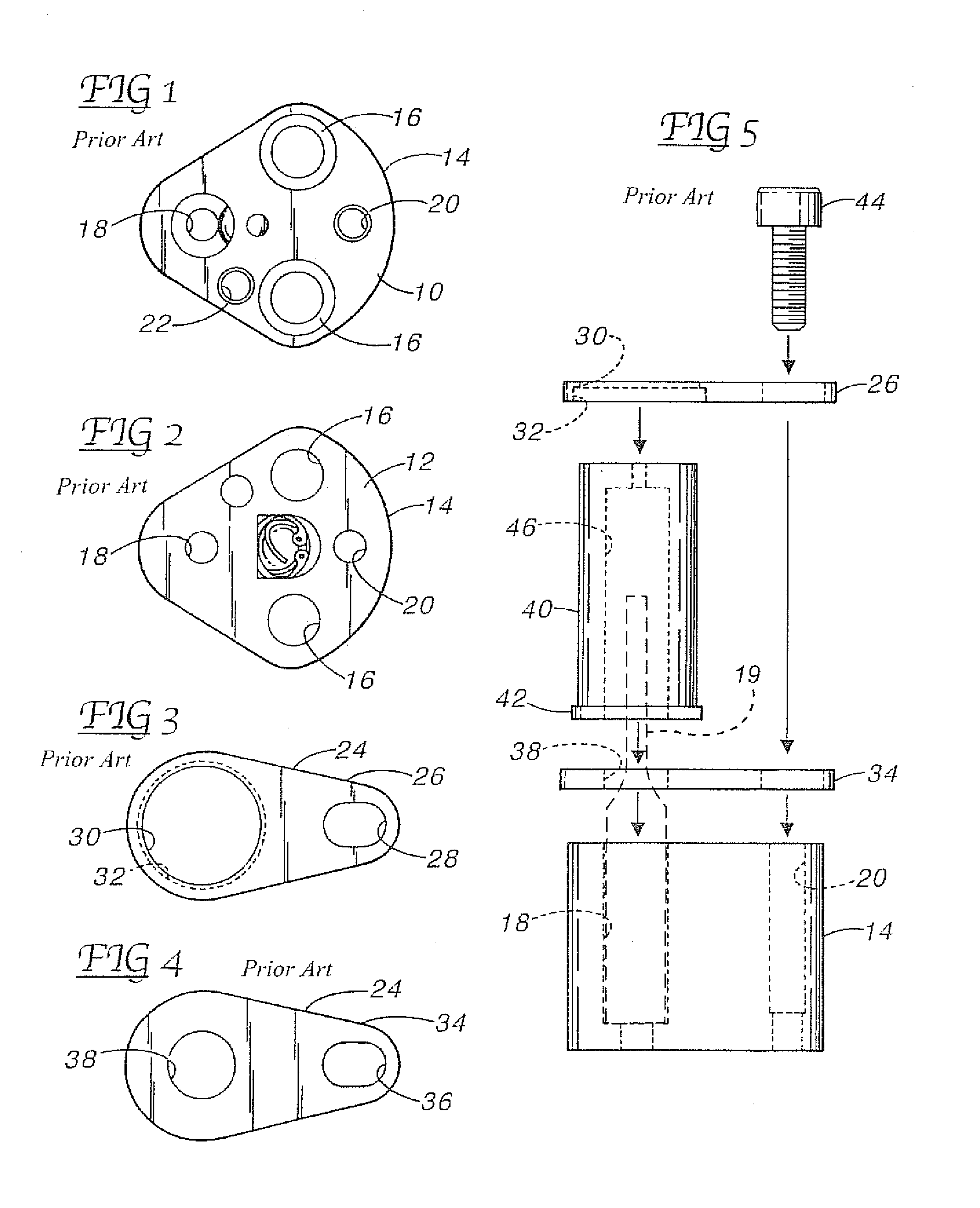
[0024]Illustrated in FIGS. 1 and 2 is the top 10 and bottom 12 of a prior art punch retainer 14. The punch retainer 14 includes counter-bored bolt holes 16 and a ball-lock punch retention hole 18. In addition, there are threaded holes 20 and 22. The prior art two-piece stripper retainer 24 in FIGS. 3 and 4 comprises an upper piece 26 having an oblong hole 28 and a circular hole 30 that is counter-bored 32 from the underside. The lower piece 34 comprises and oblong hole 36 and a circular hole 38 sized to fit over a punch P (a portion of the punch P is shown in FIG. 6).

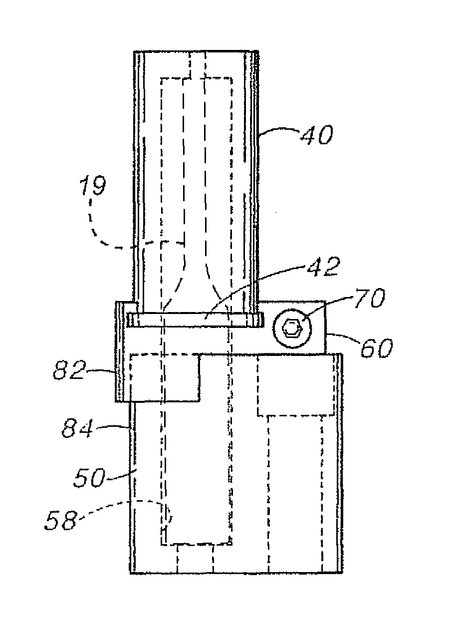
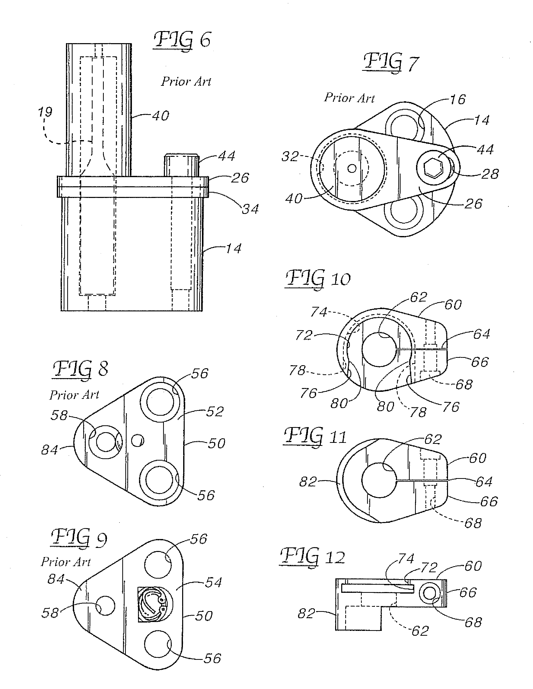
[0025]As shown in FIGS. 5, 6 and 7, the upper piece 26 and lower piece 34 are assembled to the stripper cup 40 with the cup flange 42 fitting in the counter-bore 32 and the cup extending upwardly through hole 30 of the upper piece 26. As shown in FIG. 5, the flange 42 extends outwardly from the stripper cup 40. A screw 44 passes through the oblong holes 28 and 36 and screws into threaded hole 20 in the punch retainer 14...


PUM

PropertyMeasurementUnit
outer diameteraaaaaaaaaa
diameteraaaaaaaaaa
speedaaaaaaaaaa

Abstract

A one-piece stripper retainer for plastic cup shaped strippers with a universal snap-in design that can be used with both older style and newer style punch retainers. The stripper retainer incorporates an anti-rotation heel with a snug fit around a portion of the punch retainer body and clamps to the punch itself. In a second version, the stripper retainer also clamps to the punch itself but lacks the heel. In a third version, the stripper retainer bolts to the punch retainer with a separate threaded screw. In all three versions, the plastic stripper is locked in place by the snap-in feature without any additional clamping force.

Description

[0001]This application claims the benefit of provisional patent application No. 60 / 663,695 filed Mar. 21, 2005.BACKGROUND OF THE INVENTION[0002]The field of the invention pertains to punches and dies for forming holes and depressions in metals. In particular, the invention pertains to devices and accessories for preventing work pieces from adhering to punches during high-speed high production manufacturing.[0003]Examples of modern punch retainers are shown in applicant's previous U.S. Pat. Nos. 5,357,835, 5,410,932 and Des. 351,395. Views of these punch retainers are also shown in FIGS. 1, 2, 8 and 9. Modern punches for certain applications utilize a polyurethane cup that fits over the punch and is attached to the punch retainer by a two-piece metal stripper retainer. The two-piece stripper retainer was developed to provide adequate axial support for the cup. Although inexpensively stamped from sheet steel, the two-piece stripper retainer does not rigidly and accurately retain the p...

Claims


Application Information

Patent Timeline
Patent Type & Authority Patents(United States)
IPC IPC(8): B21D45/06B26F1/14
CPCB21D45/006Y10T83/2172Y10T83/2157Y10T83/2096
Inventor MOELLERING, DAVID J.
Owner MOELLER MFG MICHIGAN
Why Eureka
Try Eureka