Removable flame heat regulating apparatus including an inner hollow shell and an outer wall for a burner of a gas stove

a technology of flame heat regulation apparatus and burner, which is applied in the field of gas stove accessories, can solve the problems of inability to use the burner of the gas stove, the use of gas stoves consuming a tremendous amount of combustive gases, and the absence of a flame heat regulation apparatus, etc., and achieves the effects of convenient maintenance, convenient cleaning, and additional versatility in us

Active Publication Date: 2010-05-04
SUN YIZHONG
View PDF24 Cites 20 Cited by
  • Summary
  • Abstract
  • Description
  • Claims
  • Application Information

AI Technical Summary

Benefits of technology

[0017]Both the inner circularly concave hollow shell and outer square wall are positioned onto the cooktop of the gas stove, wherein the inner hollow shell is further positioned to surround a gas burner. The outer square wall is positioned to surround the inner hollow shell and additionally support a cookware, wherein the cookware is placed on top sides of the extensions of the outer square wall. The extension further functions as a flame shield for preventing undesirable flame heating of a handle of the cookware in cooking.
[0029]It is a further object of the present invention to provide a flame heat regulating apparatus containing an integrated inner hollow shell and outer wall, so that the apparatus brings additional versatility in use.

Problems solved by technology

The usage of the gas stoves consumes tremendous amount of combustive gases, and also generates significant amount of carbon dioxide gases which are of total green house gases generated by human society.
However, from the illustration of the above mentioned Hammel and Gabelmann Patents, it has been discovered that there is absence of a flame heat regulating apparatus for a burner of the gas stove cooktop.

Method used


Image

  • Removable flame heat regulating apparatus including an inner hollow shell and an outer wall for a burner of a gas stove
  • Removable flame heat regulating apparatus including an inner hollow shell and an outer wall for a burner of a gas stove
  • Removable flame heat regulating apparatus including an inner hollow shell and an outer wall for a burner of a gas stove

Examples


examples

[0089]The following are examples of the present invention heat regulating apparatus for the burner of the gas stove, which are offered by way of illustration only and not by way of limitation.

[0090](1) Construction of the Heat Regulating Apparatus

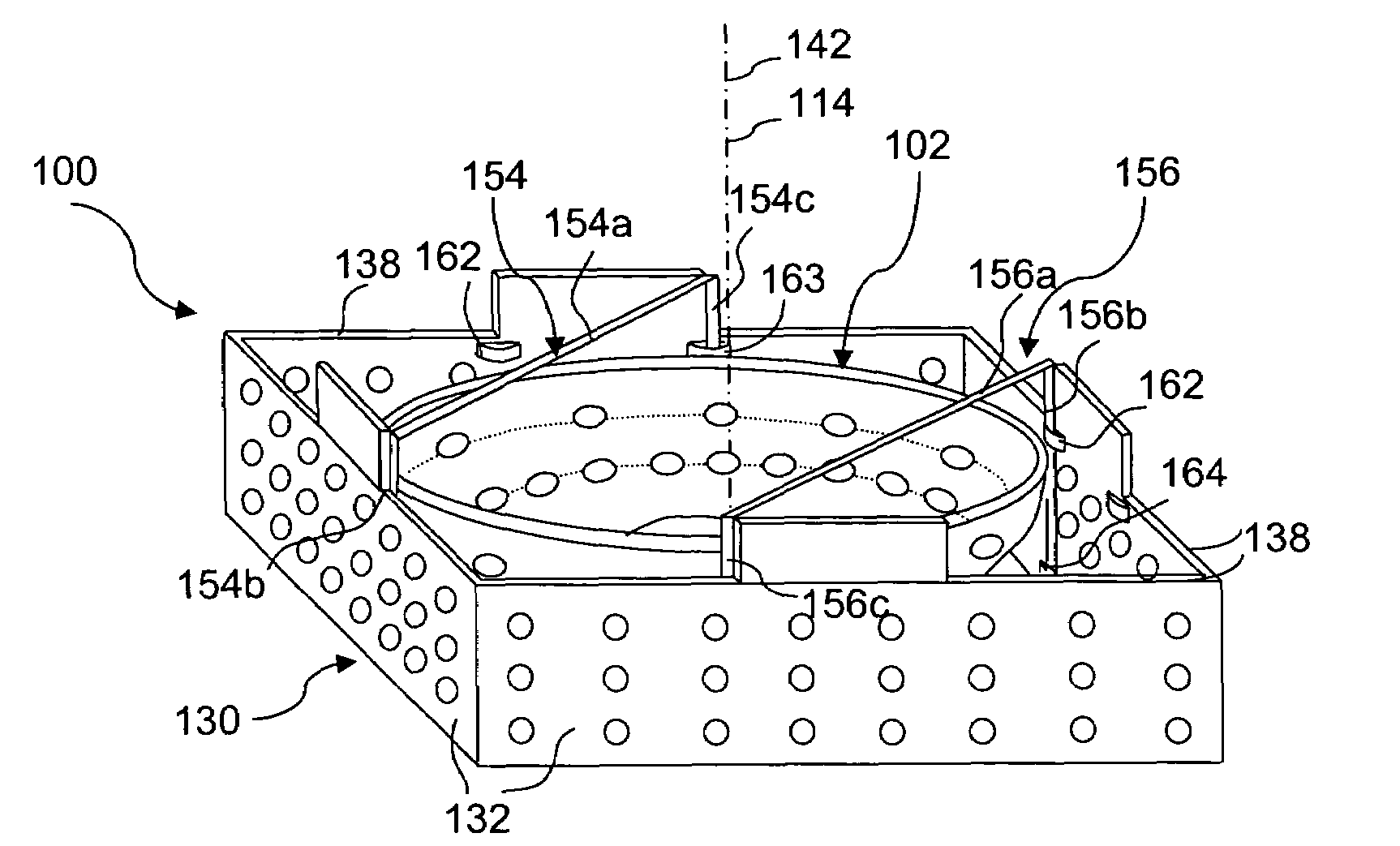
[0091]A flame heat regulating apparatus was constructed following the illustration which is disclosed for the embodiment 100 of the present invention, comprising an inner circularly concave hollow shell 102 and an outer square wall 130. The inner hollow shell 102 was comprised of a top circumference 110 having a diameter of approximately 19.2 cm, a bottom circumference 112 having a diameter of approximately 7.3 cm, and a height of 3 cm between the top and bottom circumference.

[0092]Two groups of air passages 116 were drilled through the circularly concave shell 102 with a diameter of approximately 6 mm for each air passage 116. The air passages 116 in the first group were circumferentially spaced along an upper circumference 118 adjacent th...


PUM


Abstract

A flame heat regulating apparatus for a cooktop of a gas stove, having an inner hollow shell and an outer wall which are both placed onto the stove cooktop. The shell further positioned to surround a gas burner is arcuate in shape, having a smaller sized bottom side and a larger sized top side. A plurality of air passages are through the shell, wherein the air passages are more densely distributed onto a lower part of the shell, as compared with the air passages which are less densely distributed onto an upper part of the shell. The outer wall further positioned to surround the shell has a plurality of air passages which are evenly distributed therethrough. In addition, a plurality of extensions projecting upwardly are spaced on a top side of the wall to support a cookware. The apparatus increases heating efficiency of the flame, and prevents undesirable heating of a handle of the cookware in cooking.

Description

BACKGROUND OF THE INVENTION[0001]1. Field of the Invention[0002]The present invention is related to an accessory of a gas stove which functions as a removable flame heat regulating apparatus for increase of heating efficiency of the flame in cooking.[0003]2. Description of the Prior Art[0004]Gas stoves including the cooktops are known. The following 9 United States patents and published patent applications are the closest prior art references which are related to the present invention.[0005]U.S. Pat. No. 1,156,087 issued to Kupfer on Oct. 12, 1915 for “Flame Shield For Gas Stove” discloses a cylindrical metal tube which is used as a flame shield for a burner of the gas stove. The tube is comprised of a circular wall having an upper end and a lower end, wherein a plurality of vertical slots, preferably three, are circumferentially spaced on the wall. The slots are extending upward from the lower end of the wall to an upper position of the wall, wherein one of them is arranged to fit ...

Claims


Application Information

Patent Timeline
Patent Type & Authority Patents(United States)
IPC IPC(8): F24C1/16F24C3/14
CPCF24C15/107Y02B40/00A47J36/34A47J36/36A47J37/0652F23H13/00F24B1/192F24C15/101F24C15/36
Inventor SUN, YIZHONG
Owner SUN YIZHONG
Why Eureka
Try Eureka