Process for the automatic recording of pressure-vs.-volume curves during artificial respiration

a technology of pressurevs.volume curve and automatic recording, which is applied in the field of automatic recording of pressurevs.volume curve during artificial respiration, can solve the problems of inability to ignore flow resistance, excessively long measuring time, and inability to achieve the effect of increasing accuracy

Active Publication Date: 2010-05-04
DRAGERWERK AG
View PDF45 Cites 48 Cited by
  • Summary
  • Abstract
  • Description
  • Claims
  • Application Information

AI Technical Summary

Benefits of technology

[0006]The object of the present invention is to provide a process for recording PV curves during artificial respiration with a respirator, with which the PV curve of the lung can be recorded with a greater accuracy and gently for the patient.
[0008]Volume flow peaks, at which the pressure components that are due to the flow resistance cannot be ignored, can thus be prevented from occurring, and a more accurate PV curve can thus be obtained.
[0009]Due to the fact that the medical staff is enabled to preset the set point of the breathing gas volume flow during the phase of expiration, the staff can select whether a high accuracy of measurement is preferred (in case of a set point set at a rather low value) compared with a longer phase of expiration or whether a somewhat lower accuracy is given preference compared with a shorter phase of expiration. The staff can thus run through the most suitable PV manoeuver for each patient.

Problems solved by technology

One problem in the prior-art PV measurement maneuvers is that they ignore the fact that a pressure drop is also brought about by flow resistances of the breathing gases in the airways and in the lungs.
However, these effects on the PV curve obtained, which are due to the flow resistance, cannot be ignored any longer in case of larger breathing gas volume flows.
Even though it would be possible to avoid this problem by running through a slow pressure rise ramp and a correspondingly slow expiration curve, this would require an excessively long measuring time and unduly stress the patient.

Method used


Image

  • Process for the automatic recording of pressure-vs.-volume curves during artificial respiration
  • Process for the automatic recording of pressure-vs.-volume curves during artificial respiration
  • Process for the automatic recording of pressure-vs.-volume curves during artificial respiration

Examples


Embodiment Construction

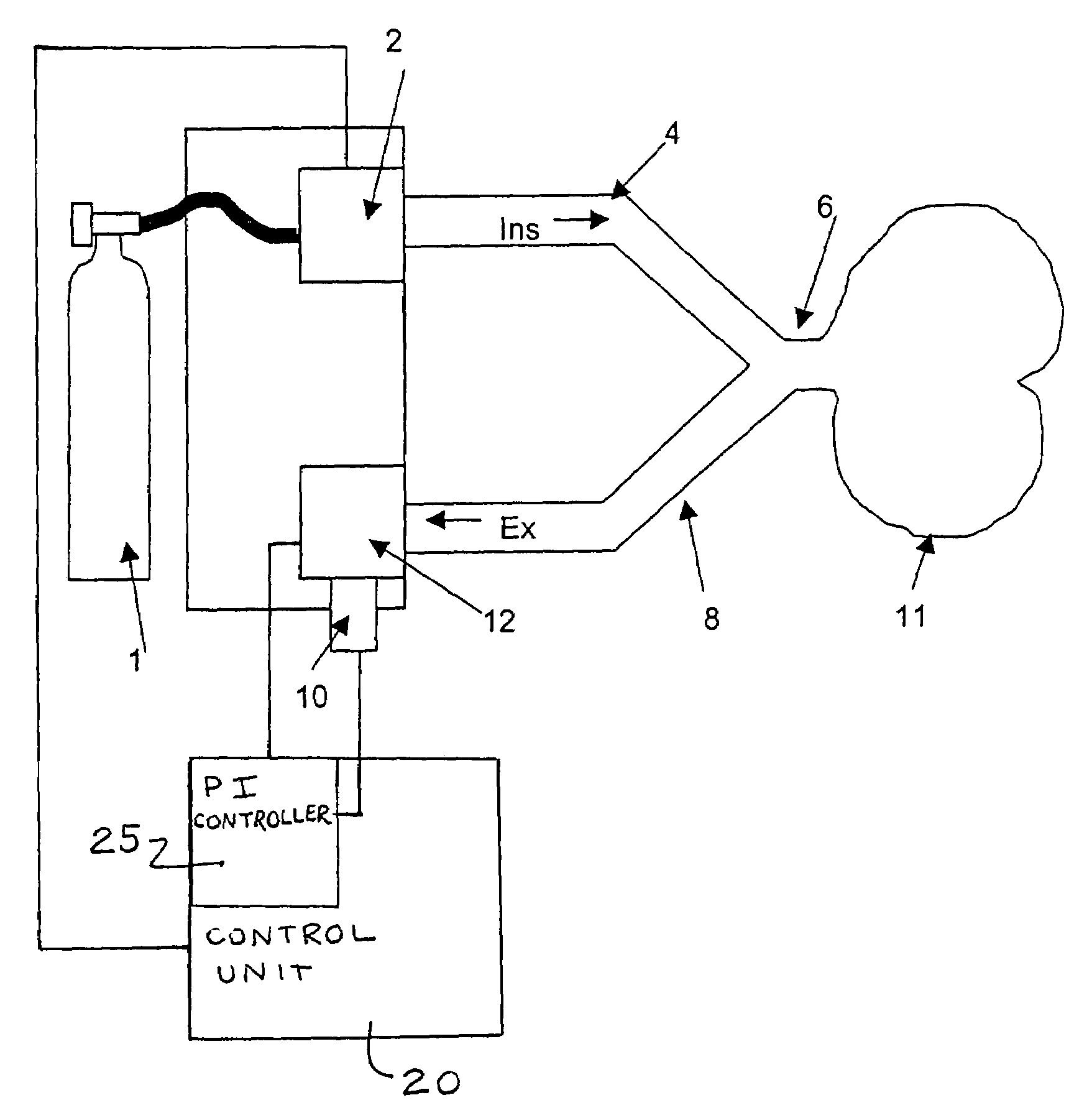
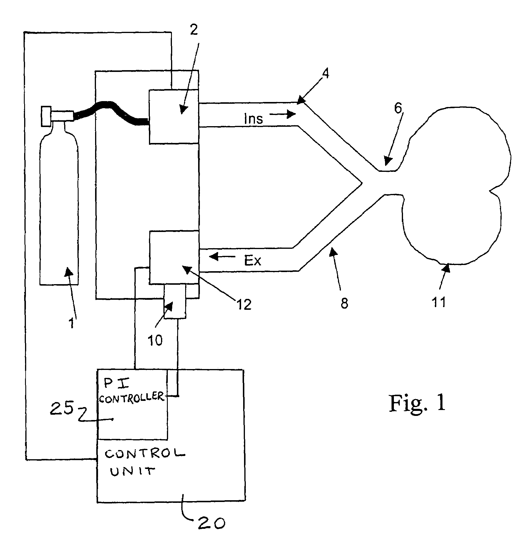
[0021]Referring to the drawings in particular, FIG. 1 schematically shows a respirator, which schematically shows only the components that are significant in connection with the present invention. The respirator is connected with a breathing gas source 1, which is connected with a source 2 for the breathing gas volume flow, which said source 2 can be readily set. The source 2 for the breathing gas volume flow is joined by an inspiration line 4, which is connected with the patient and an expiration line 8 via a Y-piece 6. The patient's lungs are designated by 11.

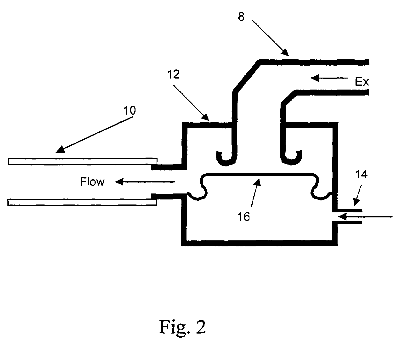
[0022]The expiration line 8 is connected with an expiration valve 12, from which the breathing gas volume flow flowing out flows through a breathing gas volume flow sensor 10.

[0023]Furthermore, a control unit 20 (shown schematically), which may be designed as a programmable processor unit, is present in the respirator. This control unit 20 may be set up for carrying out the process according to the present invention, besides ...


PUM


Abstract

A process, system and device are provided for automatically recording pressure-vs.-volume curves during artificial respiration with a respirator. The inspiration pressure is increased during the supply of a breathing gas volume flow under the control of a control unit. The resulting breathing gas volume flow rate is detected and the volume is determined from the latter by integration. The control unit compares the breathing gas volume flow detected during the phase of expiration with a preselected set point and acts on an expiration valve (12) in the expiration line (8) by means of a controller in case of deviation from the set point in order to return the breathing gas volume flow to the set point.

Description

CROSS REFERENCE TO RELATED APPLICATIONS[0001]This application claims the benefit of priority under 35 U.S.C. §119 of German Application DE 10 2004 039 711.2 filed Aug. 17, 2004, the entire contents of which are incorporated herein by reference.FIELD OF THE INVENTION[0002]The present invention pertains to a process for the automatic recording of pressure-vs.-volume curves during artificial respiration with a respirator, in which the inspiration pressure is increased during the supply of a breathing gas volume flow under the control of a control means, the resulting breathing gas volume flow is detected, and the volume is determined from the latter by integration. The present invention pertains, furthermore, to a device for carrying out the process.BACKGROUND OF THE INVENTION[0003]A PV curve (PV loop) is run through during the artificial respiration of intubated patients who are not breathing spontaneously and this is used to measure the lung. For example, a volume that is usually sub...

Claims


Application Information

Patent Timeline
Patent Type & Authority Patents(United States)
IPC IPC(8): A61M16/00A61H31/00A62B7/00A61B5/085A61B5/091
CPCA61B5/085A61M16/00A61B5/091A61M2016/0042A61M16/026
Inventor SEEGER, DIETERLORENZEN, RALFKOHL, HANS-JOACHIM
Owner DRAGERWERK AG
Why Eureka
Try Eureka